BasicSamples Package
Overview
- This is an evaluation sample project that allows you to experience the basic functions of Next Design. Please use it to evaluate and verify the digitalization of design information across the development process using Next Design and its diverse expressive capabilities that fit the field.
- All design data included in this sample is fictitious.
- This sample is intended as a reference for customers to effectively utilize this product, and we make no warranties whatsoever, including warranties of marketability and fitness for a particular purpose.
note
- There are two packages depending on your edition:
- BasicSamples Package for Enterprise Edition
- BasicSamples Package for Professional Edition
- The difference between the two packages is the presence or absence of data related to product line development.
Projects containing product line development data cannot be opened in Professional Edition.
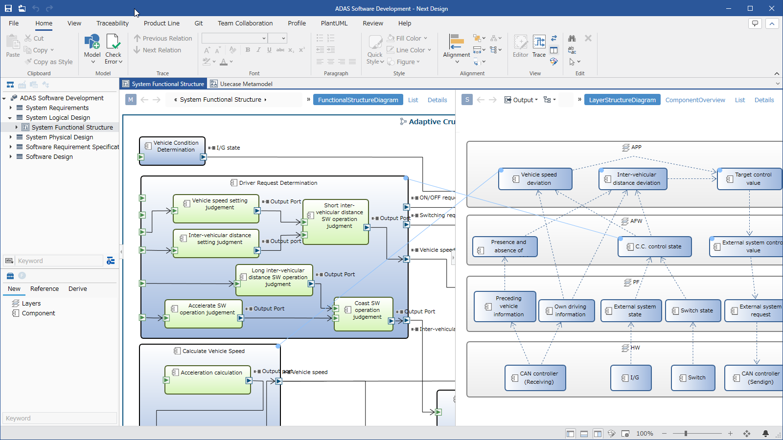
Package Contents
| File Name | Category | Description |
|---|---|---|
| ADAS_Software_Development.nproj | Sample Project | A sample project themed on advanced driver-assistance system software development. |
Overview of the Advanced Driver-Assistance System Software Development Project
-
This sample project demonstrates how to perform design from vehicle system design to software design.
-
It can be used as a reference for metamodels and view definitions, and for verifying modeling operations.
Profile Definition
- You can check the metamodel definition for "In-Vehicle System Software Development" from the Profile Navigator.
- Detailed settings for profile elements (metamodels and view definitions) can be checked from the Inspector.
Overall Metamodel Structure
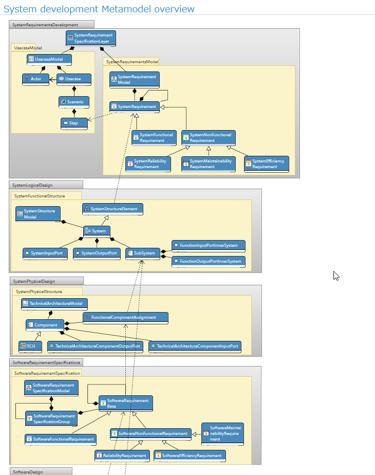
- The "In-Vehicle System Software Development Metamodel Overview" class diagram allows you to understand the overall structure of the metamodel.
- You can review the entire system design process, from system requirements development, system logic design, and system physical design, to the design content from software requirements development to software design based on these processes.
Metamodel Structure of Each Process
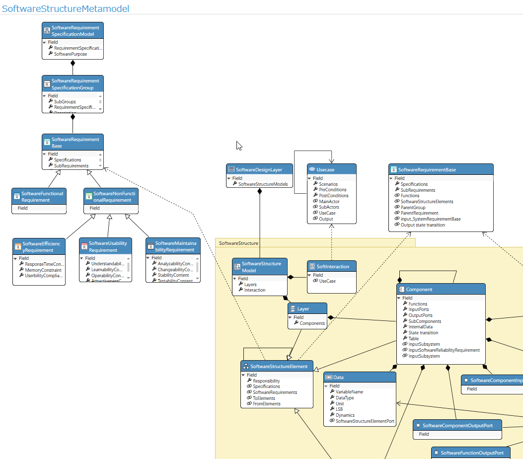
- You can also review the elements, attributes, and derivation relationships designed in each process.
- The diagram above shows the relationship between what should be defined as software requirements specifications and the software components derived from those requirements.
Model Design
- You can view a modeling example themed on the development of "Auto Cruise Control" from the Model Navigator.
Design Example: System Requirements Design
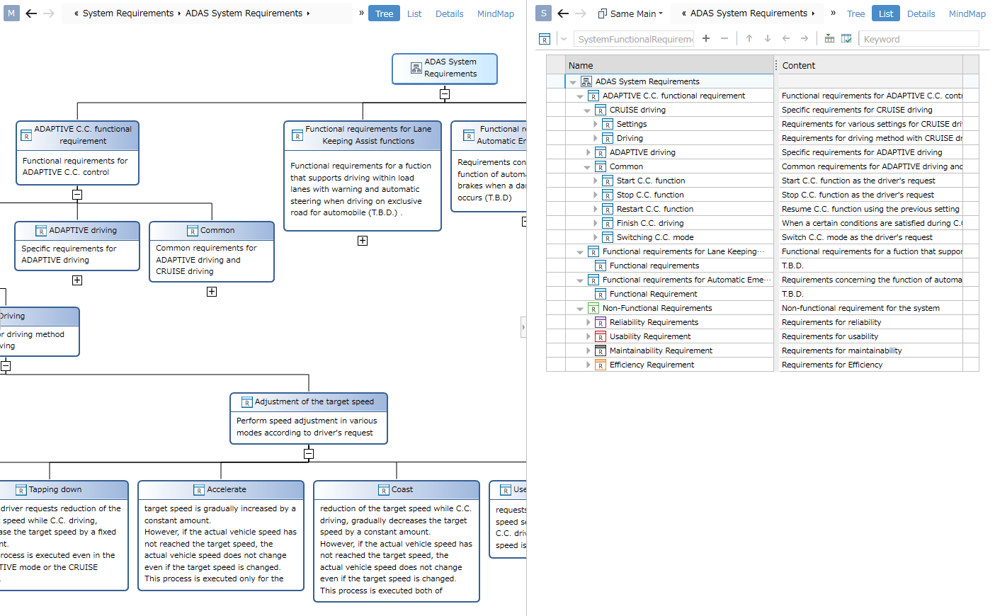
- You can design system requirements in a hierarchical structure.
- The diagram shows the same model in different views.
- The left side of the diagram shows an example of defining a tree diagram view.
- The right side of the diagram shows an example of defining a tree grid form view.
Design Example: System Logical Design
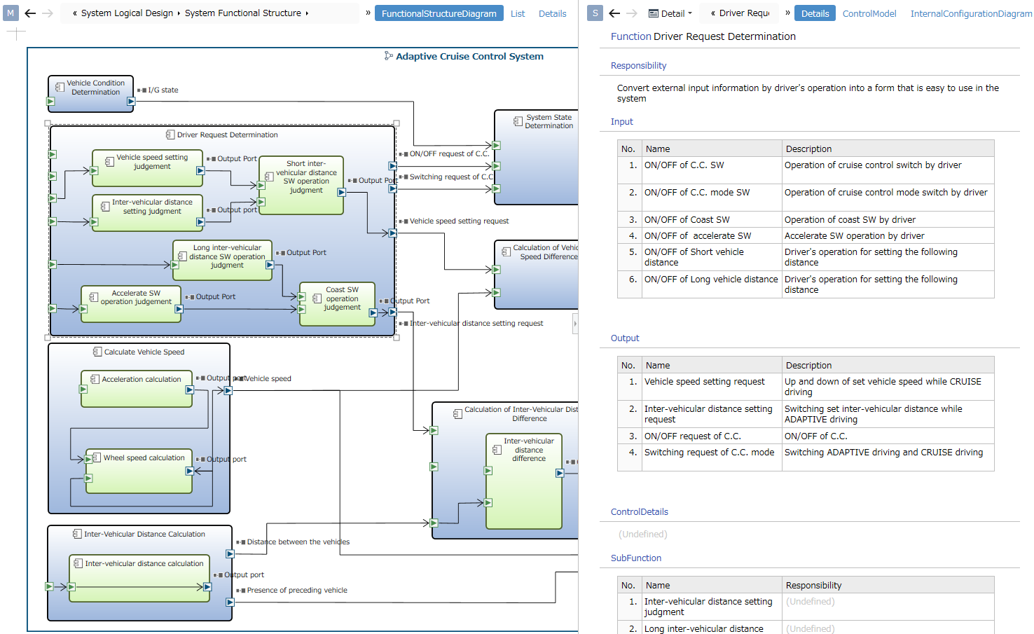
- You can design systems, functions, and their inputs and outputs.
- The left side of the diagram shows an example of defining an ER diagram view. Systems are defined as container shapes, and input/output ports are defined as port shapes.
- By selecting elements in the ER diagram, you can view details in the sub-editor.
- The right side of the diagram shows an example of defining a form view.
Design Example: Software Design
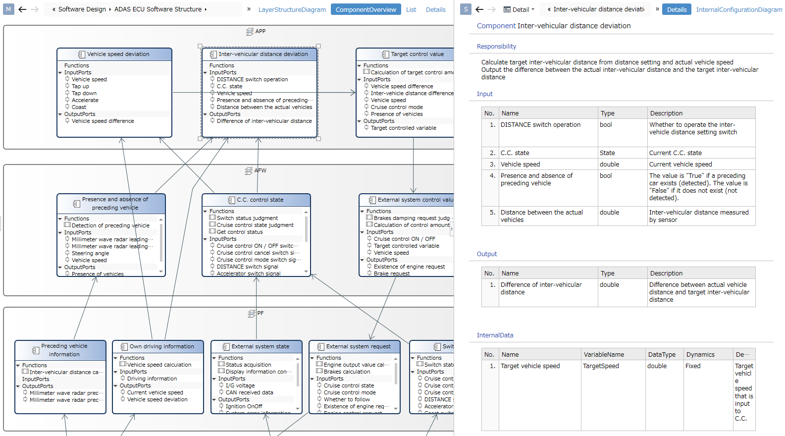
- You can design the software's layer structure and the components within each layer.
- The left side of the diagram shows an example of defining an ER diagram view. Components are defined as compartment shapes, and the compartments are defined to display functions and input/output ports.
Design Example: Trace Display Between Editors
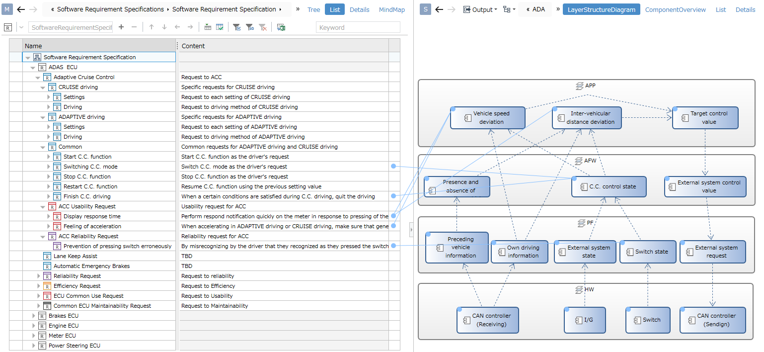
- You can set and check traces of upstream and downstream models in the editor. - The diagram displays traces of software requirements and software components.
Trace
Tree Format
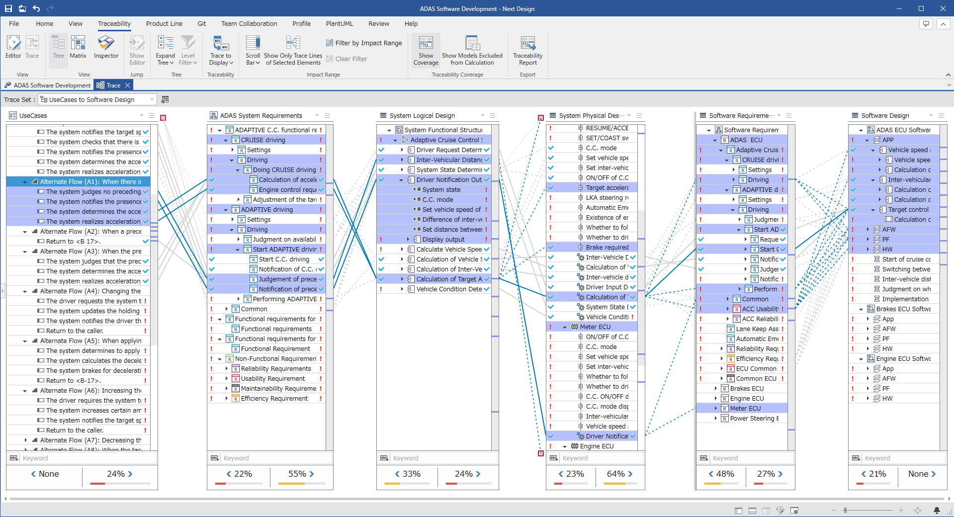
- Allows you to view traces (derivation relationships) from upstream to downstream.
- Selecting a node in the tree highlights elements with derivation relationships, allowing you to check the scope of design impact.
- Allows you to check the traceability coverage rate. You can also output a coverage rate report by executing "Output Traceability Report" on the Traceability tab of the ribbon.
Matrix Format
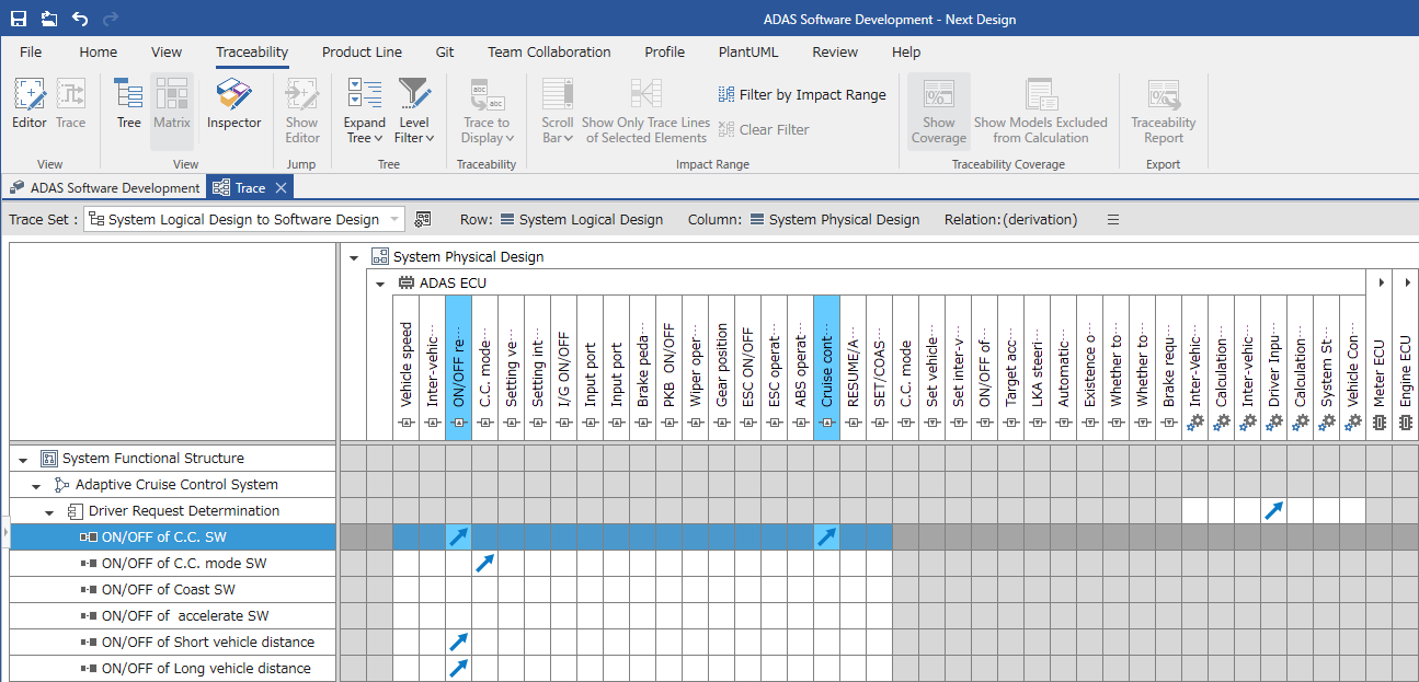
- Allows you to view traces (derivation relationships) between two artifacts.
- Selecting a node highlights elements with derivation relationships.
- Double-clicking a cell allows you to set derivation relationships.
Product Line Development (Enterprise Edition Only)
Next Design includes product line development functionality as standard.
Feature Design and Configuration
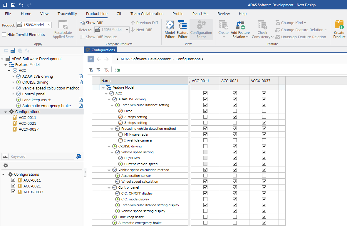
-
Feature modeling and product configuration are possible.
-
Defined features can be enabled or disabled by products by associating them with the model.
When Applying Products
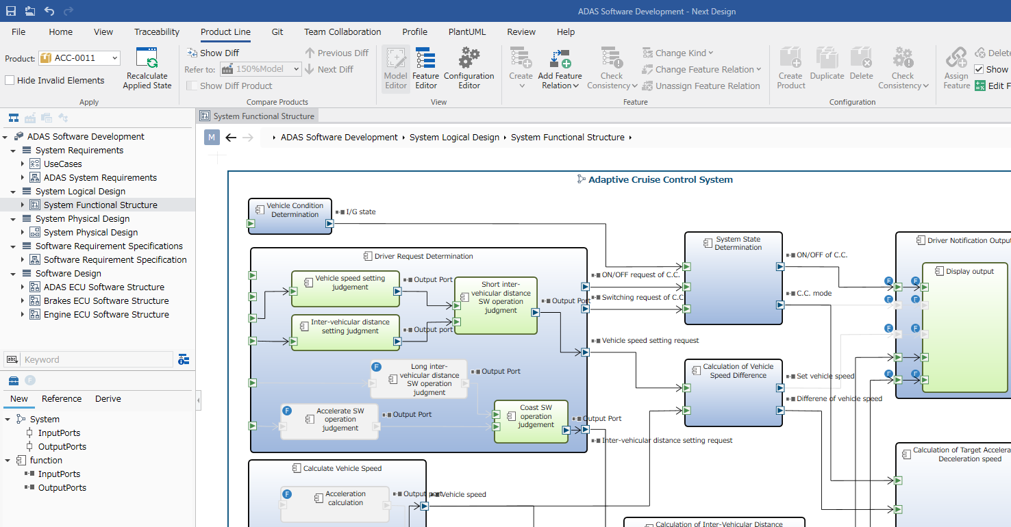
- You can select the product to apply from the "Product" dropdown on the Product Line tab of the ribbon.
- Models that are disabled by applying a product are displayed in a toned-down state.
- This allows you to design and represent the ON/OFF status of various functions within a single project.