Package UmlSysmlSample
Overview
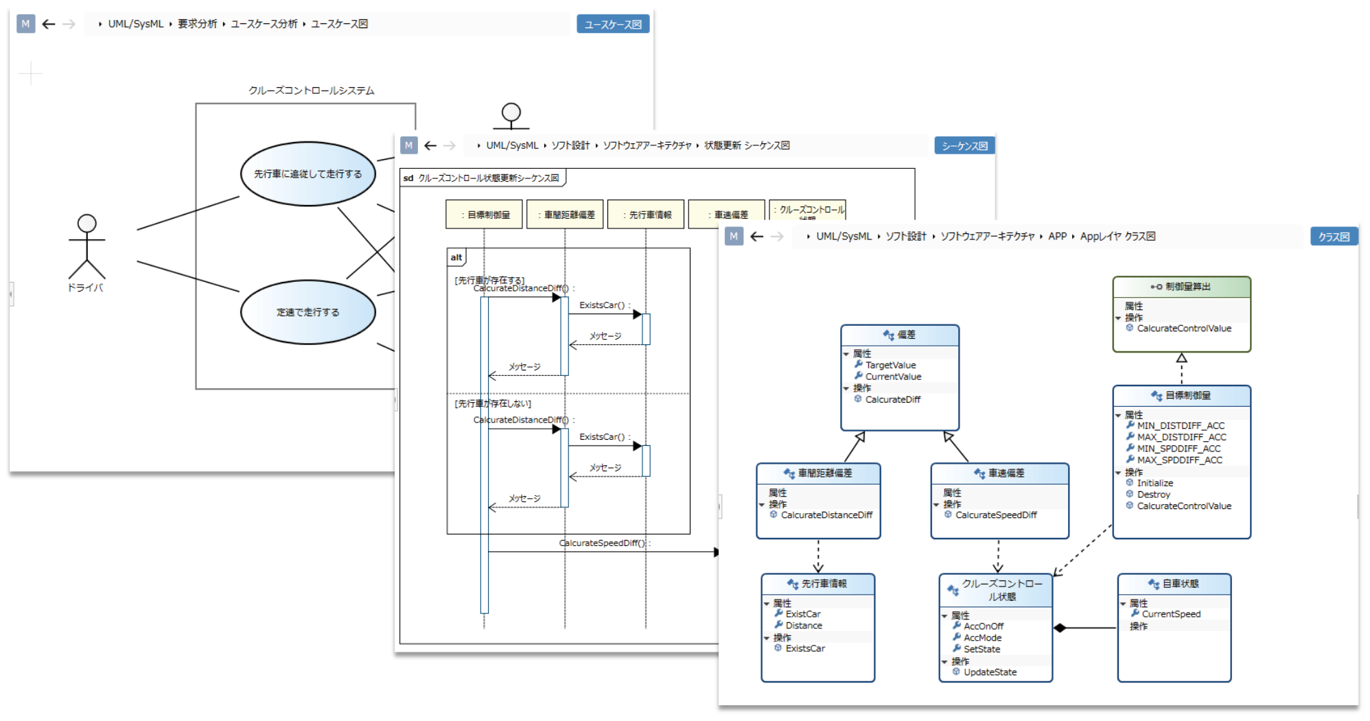
- This is a sample that can describe diagrammatic representation of UML/SysML.
- In a sequence diagram, there are restrictions such as the operation of the inheritance source of the class cannot be specified in the message.
- All design data included in this sample is fictitious.
- Samples are intended to be used as a reference for customers to effectively use this product, and we do not make any guarantees, including warranties of marketability and suitability for specific purposes. .
info
The release of this package has ended because the successor package UML/SysML has been released.
If you are new to UML/SysML modeling, please use the successor package.
Package contents
| File Name | Category | Description |
|---|---|---|
| UML_SysML.iproj | Sample Project | This is a sample describing UML/SysML diagrams. |
| UML_SysML.iprot | Template | This is a template for describing UML/SysML diagrams. |
| UML_SysML.iprof | Profile | Profile for UML/SysML. You can also import it into any project. |
List of figures that can be described
- Shows diagrams and restrictions that can be described in this package (partially, details will be described later).
| Target | Classification | Diagram | Correspondence | Restrictions |
|---|---|---|---|---|
| All | - | - | ・Stereotypes cannot be represented graphically. Check/edit in sub-editor or property inspector. | |
| UML | Structure | Class Diagram | ✓ | ・Static/abstract attributes cannot be represented on the diagram. Check/edit in sub-editor or inspector. - Relevant end names and multiplicity cannot be expressed. ・Attribute types, initial values, operation types, parameters, etc. cannot be represented on diagrams. Check and edit with the sub-editor or inspector. |
| Package Diagram | ✓ | - | ||
| Object diagram | ✗ | Not supported. | ||
| Behavior | Usecase Diagram | ✓ | - | |
| Sequence Diagram | ✓ | ・The use of state invariants, duration constraints, and interactions cannot be defined. - Messages cannot be connected from frames. - Elements cannot be copied and pasted. - The operation from which the class is inherited cannot be specified in the message. | ||
| Communication Diagram (Collaboration Diagram) | ✗ | Not supported. | ||
| Statemachine Diagram | ✓ | ・Concurrent states cannot be defined. - Triggers and guards can be described on the diagram, but the notation format differs from the UML standard. ・The effect cannot be expressed on the diagram. Check and edit with the sub-editor or inspector. | ||
| Activity Diagram | ✓ | ・Swimlanes cannot be defined. | ||
| Implementation | Component Diagram | ✓ | ・Interfaces are represented differently from the UML standard (classes cannot be displayed and are represented by circles). | |
| Deployment Diagram | ✓ | - | ||
| SysML | requirement | Requirement Diagram | ✓ | ・The ID of the requirement cannot be represented on the diagram. Check and edit with the sub-editor or inspector. |
| Structure | Deployment Diagram | ✓ | (similar to UML deployment diagram)) | |
| Block definition diagram | ✓ | ・Input/output ports of blocks cannot be placed as shapes. Write in compartments. -Relevant end names and multiplicity cannot be described. | ||
| Internal Block Diagram | ✓ | ・The block type is a rectangular label notation. -Relevant end names and multiplicity cannot be described. | ||
| Package Diagram | ✓ | (similar to UML package diagram) | ||
| Composite diagram | ✓ | (same as UML component diagram) | ||
| Profile diagram | ✗ | Not supported. | ||
| behavior | Usecase Diagram | ✓ | (similar to UML use case diagram) | |
| Activity Diagram | ✓ | (similar to activity diagram in UML) | ||
| Statemachine Diagram | ✓ | (similar to UML State Machine Diagram) | ||
| Sequence Diagram | ✓ | (similar to sequence diagram in UML) | ||
| Interaction overview diagram | ✗ | Not supported. | ||
| Timing diagram | ✗ | Not supported. | ||
| Parametric | Parametric Diagram | ✓ | ・ Constraint content and constraint parameter type display are different from the SysML standard. |
Describeable model overview
- You can design your model namespace by adding packages in the model navigator.
- You can add each figure under the package and model it.
- Added models are placed under packages and diagrams.
- Some diagrams, such as class diagrams, do not delete the model itself even if you delete an element from the diagram. If you want to delete a model, please delete it from Ctrl+D key or model navigator.
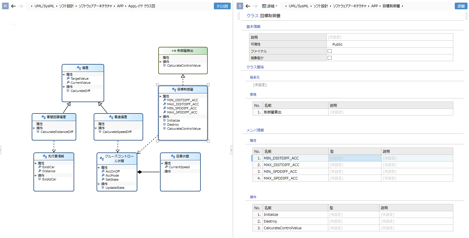
Class diagram
Overview
- Can describe classes and interfaces, their attributes and operations.
- You can describe relationships between classes (such as inheritance and aggregation).
- Dependency, association, association (unidirectional), ownership, aggregation, inheritance, and realization can be described.
- Details such as class stereotypes can be described in sub-editors and inspectors.
- Can describe class description, visibility, final, abstract type, inherited from, implemented interfaces, attributes and operations.
Restrictions
- Static/abstract attributes cannot be represented on diagrams. Check and edit with the sub-editor or inspector.
- Relevant end names and multiplicity cannot be expressed.
- Attribute types/initial values, operation types/parameters, etc. cannot be represented on diagrams. Check and edit with the sub-editor or inspector.
- For types, define primitive types such as int and string separately before specifying them.
- Lollipop display of the interface is not possible.
- Once added, the type of relationship between classes (dependence, ownership, aggregation, etc.) cannot be changed (recreate it).
- You cannot attach note anchors to class attributes, operation elements, and connectors.
- Connectors cannot express ownership relationships between packages and classes.
- A class can be specified as the inheritance source of an interface.
- You could define circular inheritance.
- Even a Final class can define a subclass.
- Associated classes cannot be defined.
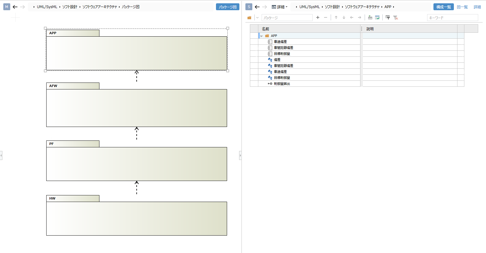
Package Diagram
Overview
- Can describe package structure and dependencies.
- In the sub-editor, you can check the list of package content components.
Restrictions
- none
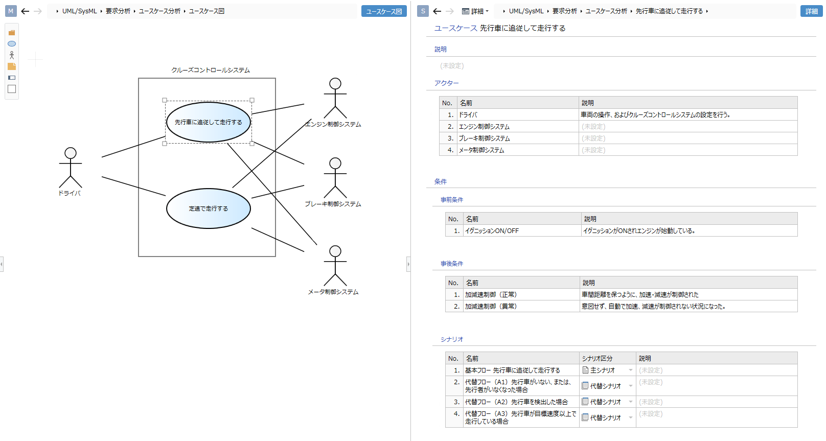
Usecase diagram
Overview
- You can write standard use case diagrams such as use cases and actors.
- You can check detailed information in the sub-editor by selecting the written element.
- You can write pre-conditions, post-conditions and scenarios in the use case detail view.
Restrictions
- Substitute rectangular shapes for system boundaries and packages.
Sequence Diagram
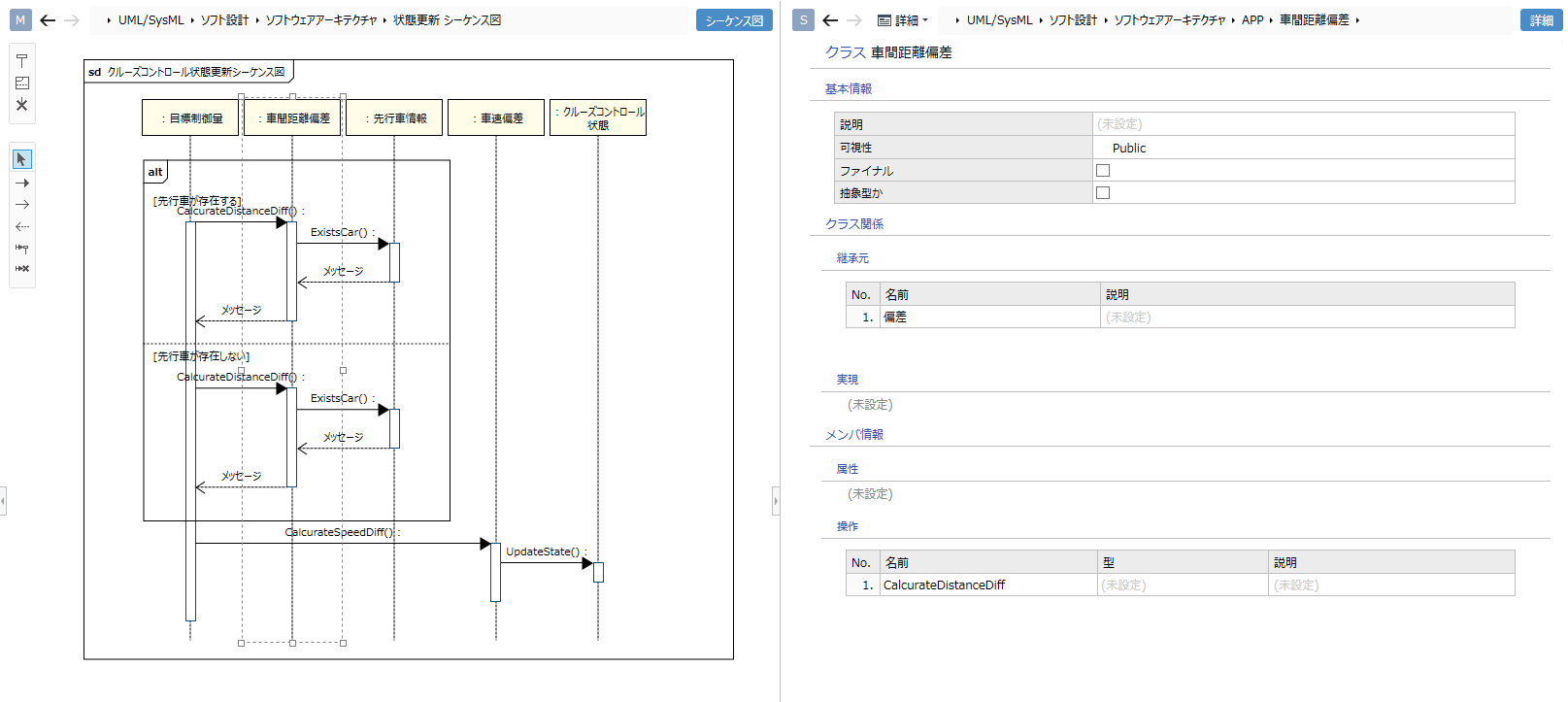
Overview
- Sequence diagrams can describe model behavior.
- You can write lifelines, composite fragments and discards.
- You can write synchronous, asynchronous, reply, produce and destroy messages.
- Actors, components, and classes can be placed as lifelines by dragging and dropping them from the model navigator.
- When you connect a message, you can specify the port of the component and the operation of the class as the message content.
- You can check detailed information in the sub-editor by selecting the written element.
Restrictions
- Use of state invariants, duration constraints, and interactions cannot be defined.
- It is not possible to connect messages from frames.
- Elements cannot be copied and pasted.
- The operation from which the class inherits cannot be specified in the message.
- Unable to precisely define the order of messages in a sequence (called GeneralOrdering)
State Transition Diagram
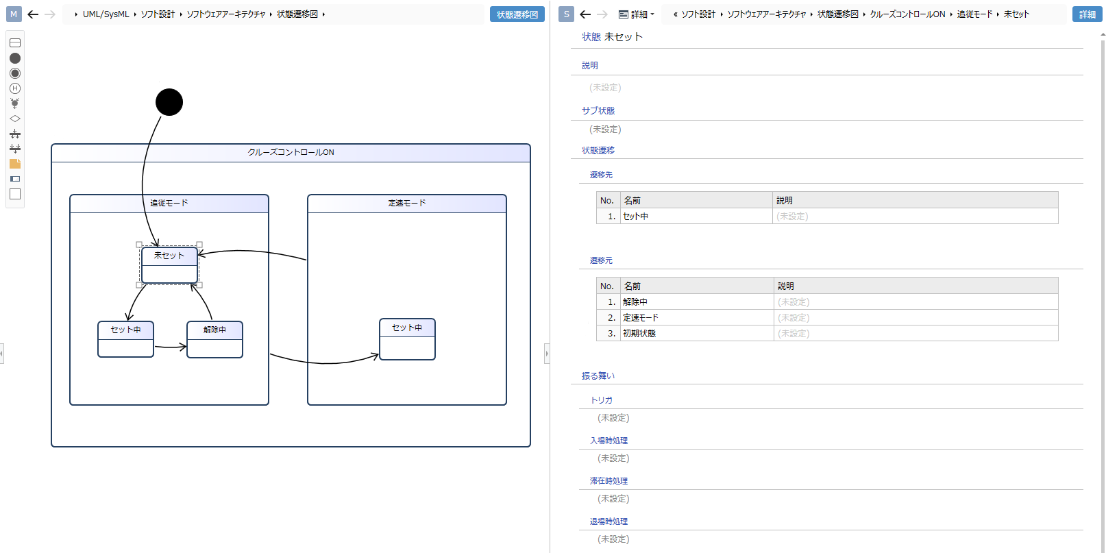
Overview
- You can describe transitions from state to state.
- State (entry point, exit point), start, end, history, integration, selection, parallel, merge can be described.
- You can check detailed information in the sub-editor by selecting the written element.
Restrictions
- Concurrent states cannot be defined.
- Trigger guards can be described graphically, but the notation format differs from the UML standard.
- Effects cannot be represented on the diagram. Check and edit with the sub-editor or inspector.
- State areas, list displays, and functions cannot be expressed or described.
- Cannot be converted to a state transition table.
Activity Diagram
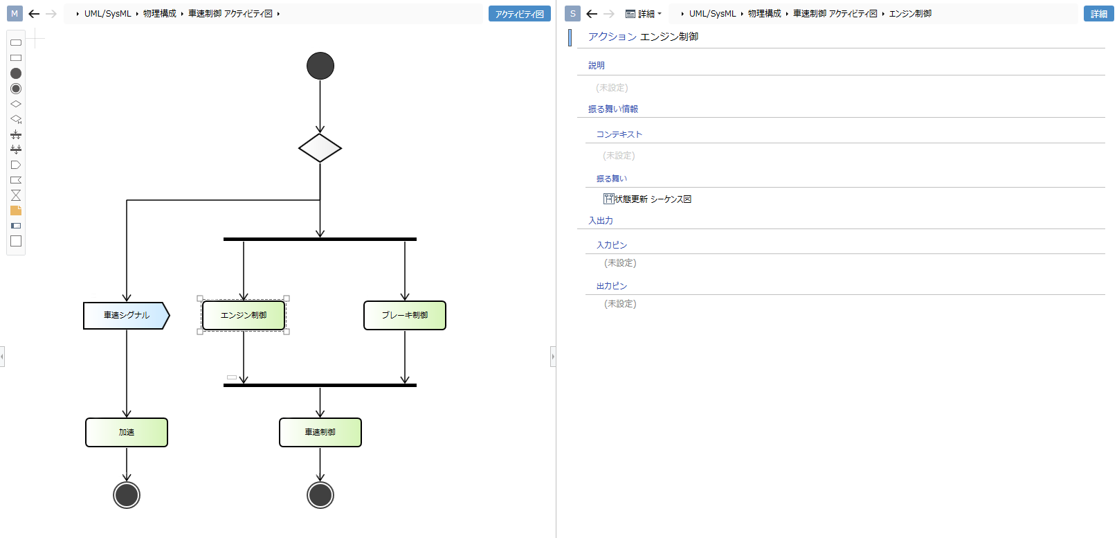
Overview
- You can describe the flow of control in activity diagrams.
- Action, Object, Start, End, Decision, Merge, Parallel, Join, Signal Send, Signal Receive, Time Event Acceptance can be described.
- In addition, you can specify input/output action pins for actions, etc.
Restrictions
- Swimlanes are not supported.
- The display position of the action pin is different from the UML standard (it is displayed so as to overlap the node).
- Parallel/Merge cannot be switched vertically. To express it, transform each shape by resizing.
- Interruptible areas, extended areas, and exceptions cannot be described.
Component diagram
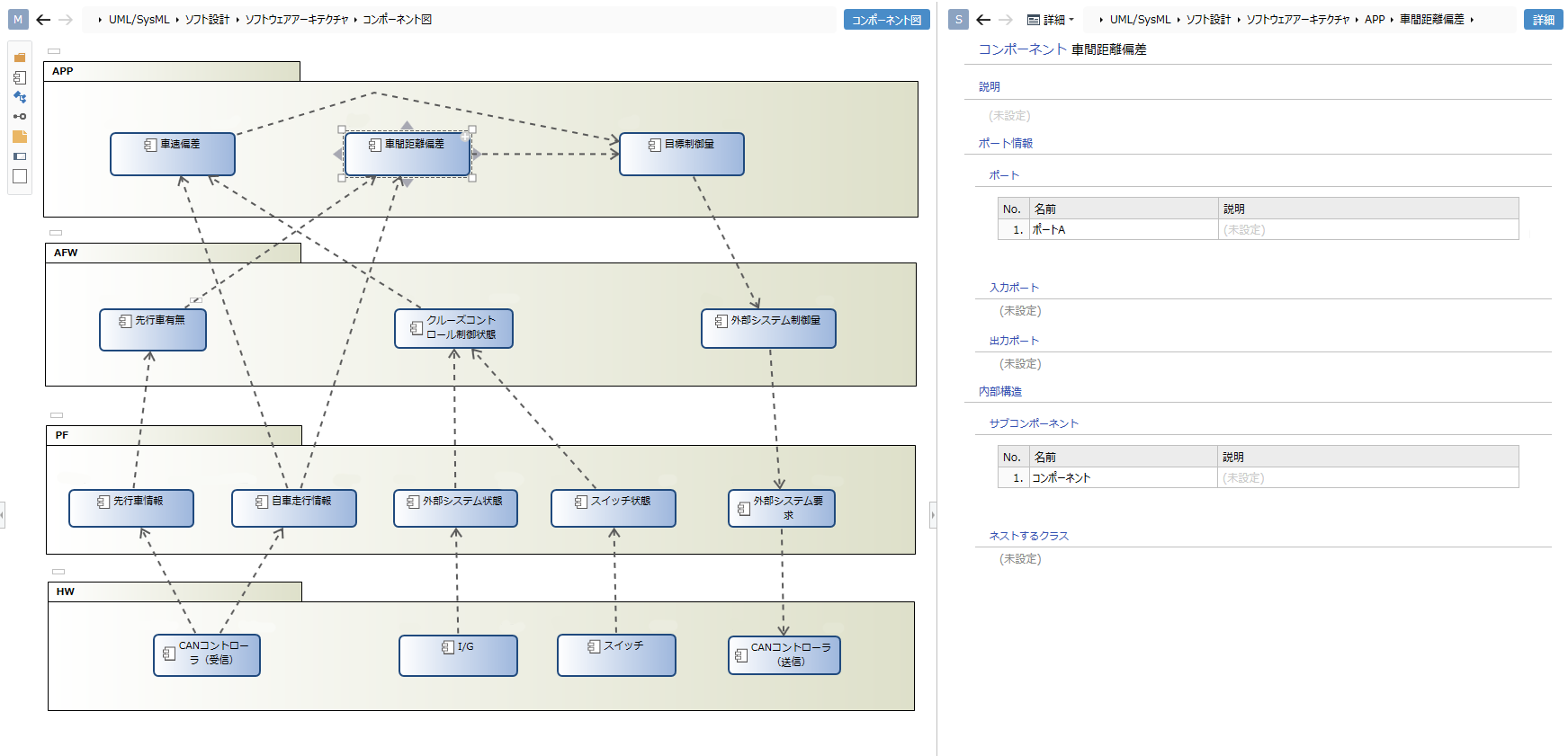
Overview
- You can describe the internal structure of components and the interactions between components.
- Can describe packages, components (ports), classes and interfaces.
- You can describe relationships between packages and components (dependence, association, association (unidirectional), inheritance).
Restrictions
- Interfaces are represented differently from the UML standard (classes cannot be displayed and are represented by circles).
- It is not possible to add a port to a part (it is automatically reflected by adding it to a type component).
- Ports can be directly connected by connectors without going through an interface.
Deployment Diagram
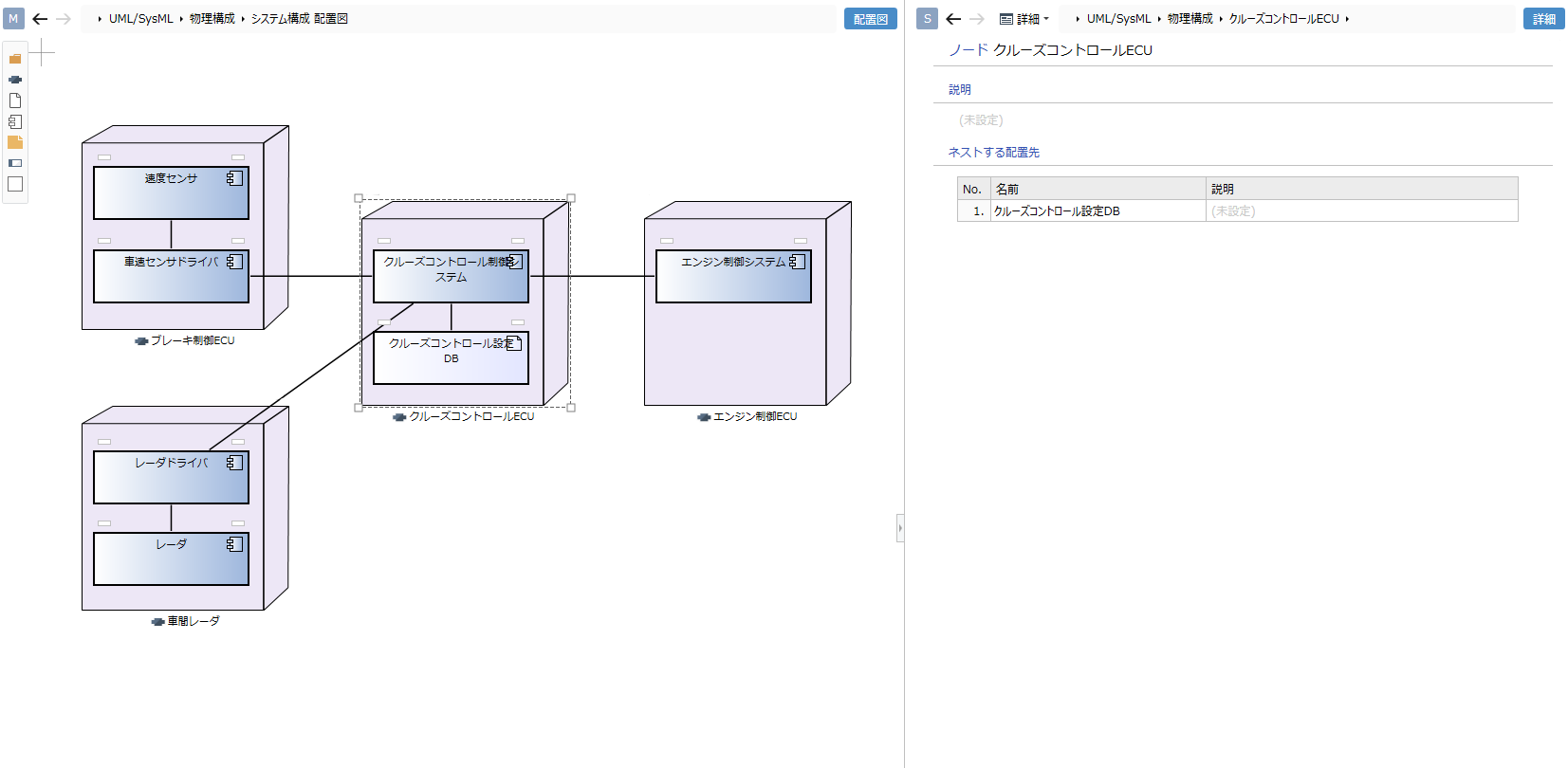
Overview
- You can describe the physical layout of your system.
- Can describe packages, nodes, artifacts and components.
- You can describe relationships (dependencies, associations) between nodes and components.
Restrictions
- Associated stereotypes (e.g. Deploy) cannot be represented graphically. Check and edit with the sub-editor or inspector.
Requirements diagram
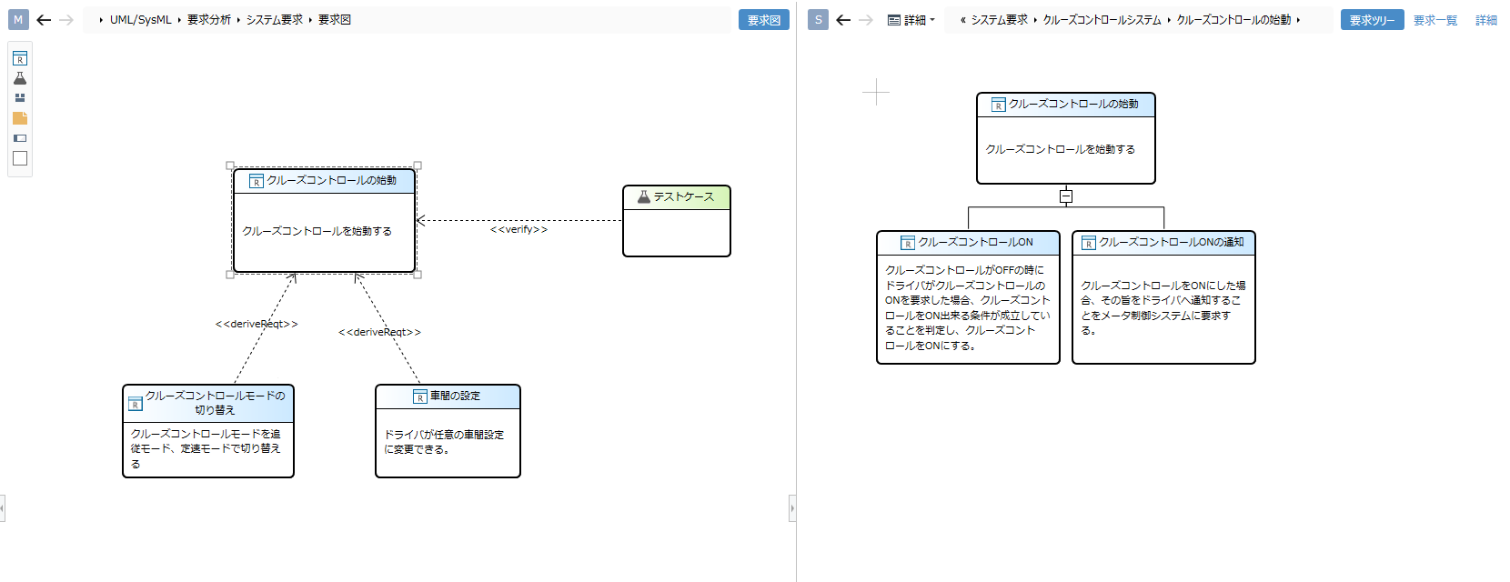
Overview
- You can describe the structure and details of requirements in the requirement diagram.
- Describe requirements and relationships between requirements (derived requirements, copies, satisfactions, refinements, validations, traces).
- Describe test cases and relationships (satisfaction, refinement, verification, tracing) to requirements.
- Use cases, components, classes, etc. can be placed as elements by dragging and dropping them from the model navigator.
- Can describe relationships between elements and requirements (satisfaction, refinement, verification, tracing).
- When you select a requirement or test case, you can describe details in a tree structure in the sub-editor.
Restrictions
- Request IDs cannot be represented on the diagram. Check and edit with the sub-editor or inspector.
Block Definition Diagram
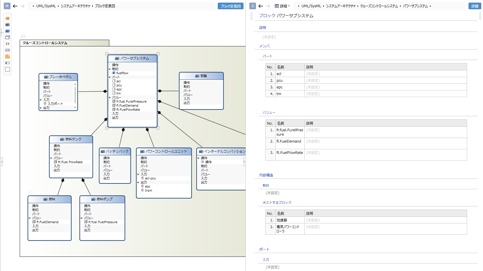
Overview
- You can describe the structure of the system in a block definition diagram.
- You can describe packages, blocks, constraint blocks, value types, units and quantity types.
- You can describe the relationship (owned, aggregated, related, dependent) of each element.
Restrictions
- Block input/output ports cannot be placed as shapes. Write in compartments.
- Relevant end name and multiplicity cannot be described.
Internal block diagram
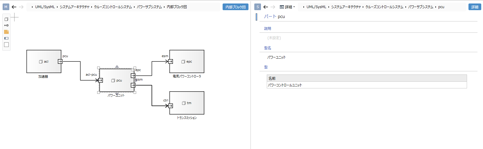
Overview
- You can describe the internal structure of the block. Create a diagram under the block and describe it.
- Parts (input ports, output ports) and interfaces can be described.
Restrictions
- Relevant end name and multiplicity cannot be described.
- It is not possible to add a port corresponding to a part (it is automatically reflected by adding it to a type component).
Parametric diagram
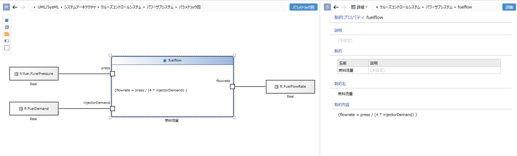
Overview
- Constraints (formulas, etc.) between systems can be described in parametric diagrams, and parameters, etc. can be checked.
- Constraints (constraint parameters) and values can be described.
- Constraints can describe constraints.
- You can describe the relationship (bind) between values and constraint parameters.
Restrictions
- Constraint content and type display of constraint parameters are different from the SysML standard.
- The display position of the constraint parameter is different from the UML standard (it is displayed so as to overlap the node).