State Machine Diagram/State Transition Table
Overview
State machine diagrams can be used to describe the state and behavior of a system or class. In addition to state machine diagrams, state transition tables can also be used, allowing for seamless design by switching between them.
The state transition table highlights areas with and without transitions, and allows you to identify transitions where triggers are not defined. Furthermore, by noting information that the trigger should be ignored or is impossible instead of the transition, you can design without omissions.
This page explains the operations for using state machine diagrams and state transition tables in the following order.
- Placing a State Machine Diagram
- Defining States
- Defining Transitions
- Describing Design Information in a State Transition Table
Furthermore, the following functions are provided to assist user modeling.
These will also be explained in order.
- Validating the Model
- Setting Display Contents
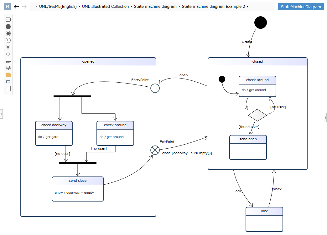
Placing a State Machine Diagram
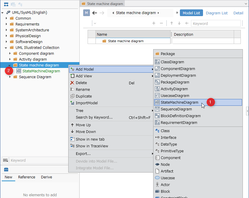
To place a state machine diagram, follow these steps:
-
Select a package in the Model Navigator and click [Add Model] > [State Machine Diagram] in the context menu.
-
The state machine diagram will be placed as a child element of the selected package.
In the current version, if the display scale in the display settings is set to a value greater than 100%, some of the text in the state transition table cells may be cut off. To avoid this issue, please set the display scale in the display settings to 100%.
For other restrictions, please refer to here.
Defining a State
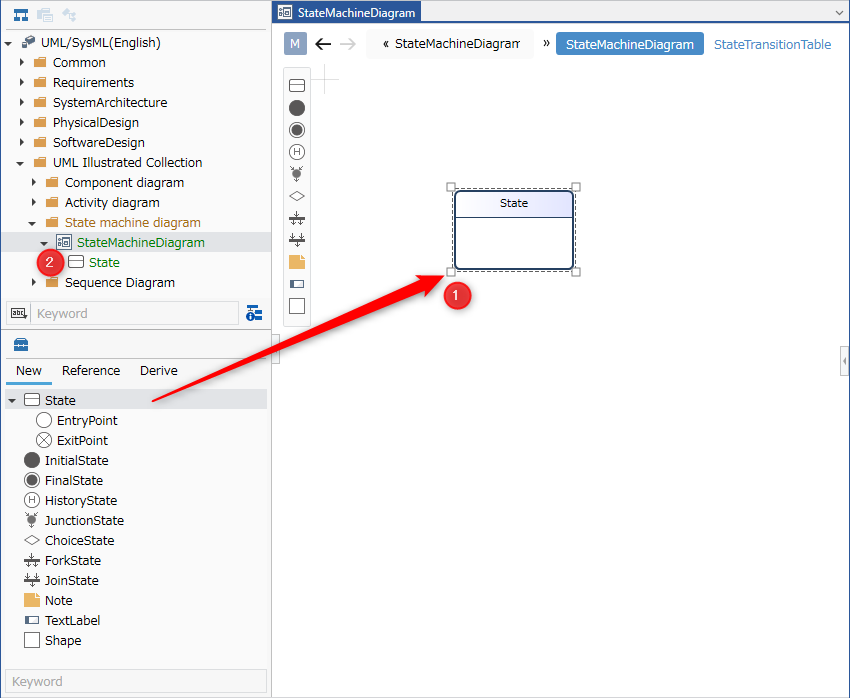
To define a state, follow these steps:
-
Drag and drop [State] from the toolbox onto the displayed state machine diagram.
-
A new state will be added as a child element of the displayed state machine diagram or state.
The following elements displayed in the toolbox can be placed in the state machine diagram.
| Icon | Name |
|---|---|
 | State |
 | Entry point |
 | Exit point |
 | Start |
 | End |
 | History |
 | Merge |
 | Selection |
 | Parallel |
 | Merge |
 | Note |
 | Label |
 | Shape |
Entry and exit points are placed as port shapes of the following elements:
- State
Adding behavior to the state
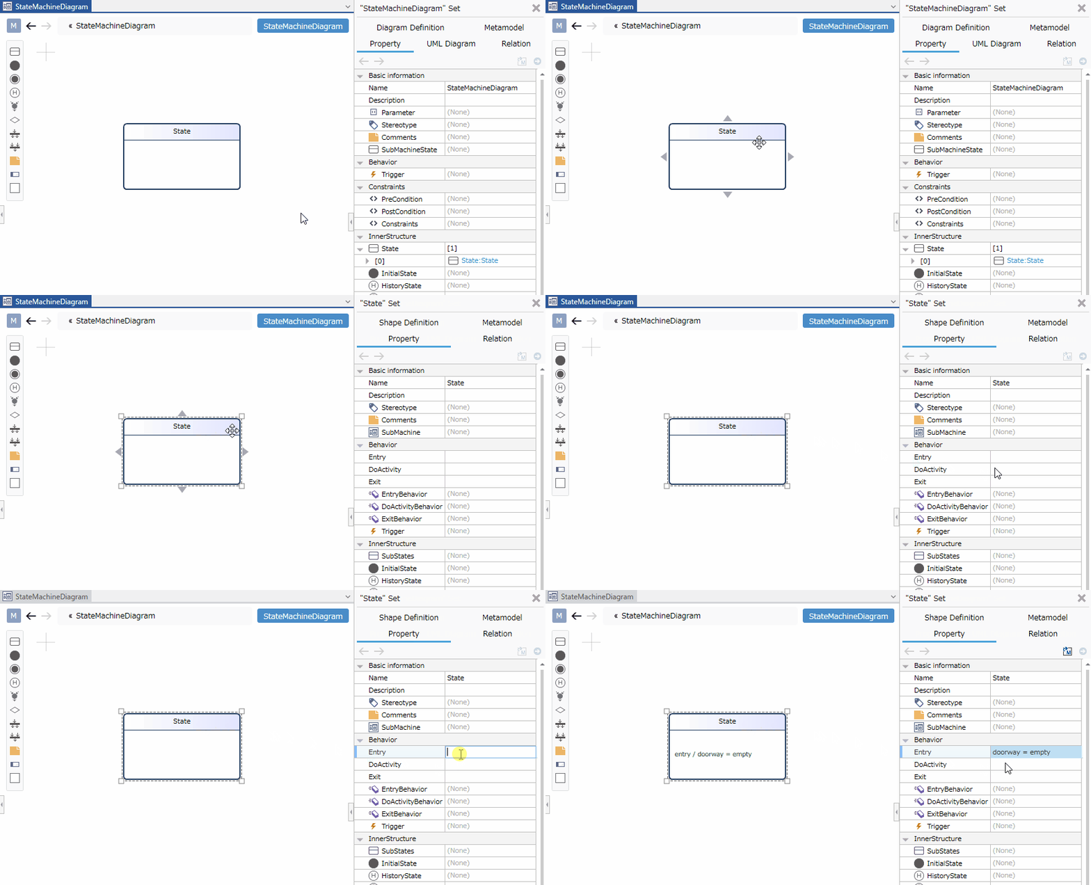
To add processing upon entry, follow these steps:
- Select the state.
- Double-click the [Shake Dance] > [Entry processing] field in the Property Inspector to enter edit mode.
- Write the entry processing and confirm the edit. The entry processing will be set for the state and displayed on the state machine diagram.
When you enter text in the state body on the state machine diagram, the text is parsed according to the notation format and reflected in each field value of the state.
Of course, changing each field value will be reflected in the text on the diagram.
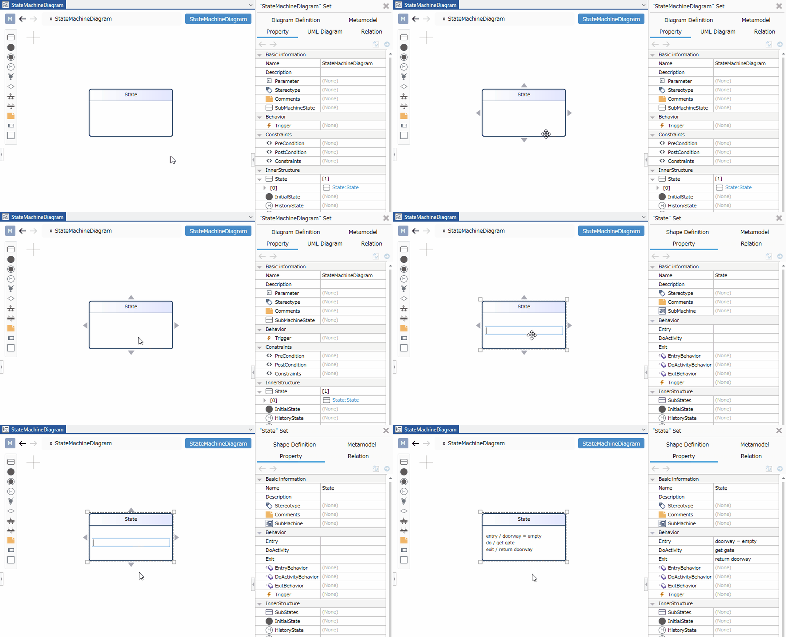
Correspondence between State Behavior, Text Notation Format, and Field Values
Behavior for a state is displayed and parsed according to the following format:
-
Format:
<Behavior> ::= ['entry/'<Entry Processing>]['\n']['do/'<Stay Processing>]['\n']['exit/'<Exit Processing>] -
Example
Entry Processing:set display on
Stay Processing:show distance
Exit Processing:set display off
In this case, the following text will be displayed.
entry/set display on
do/show distance
exit/set display off
Adding a Stereotype to a State
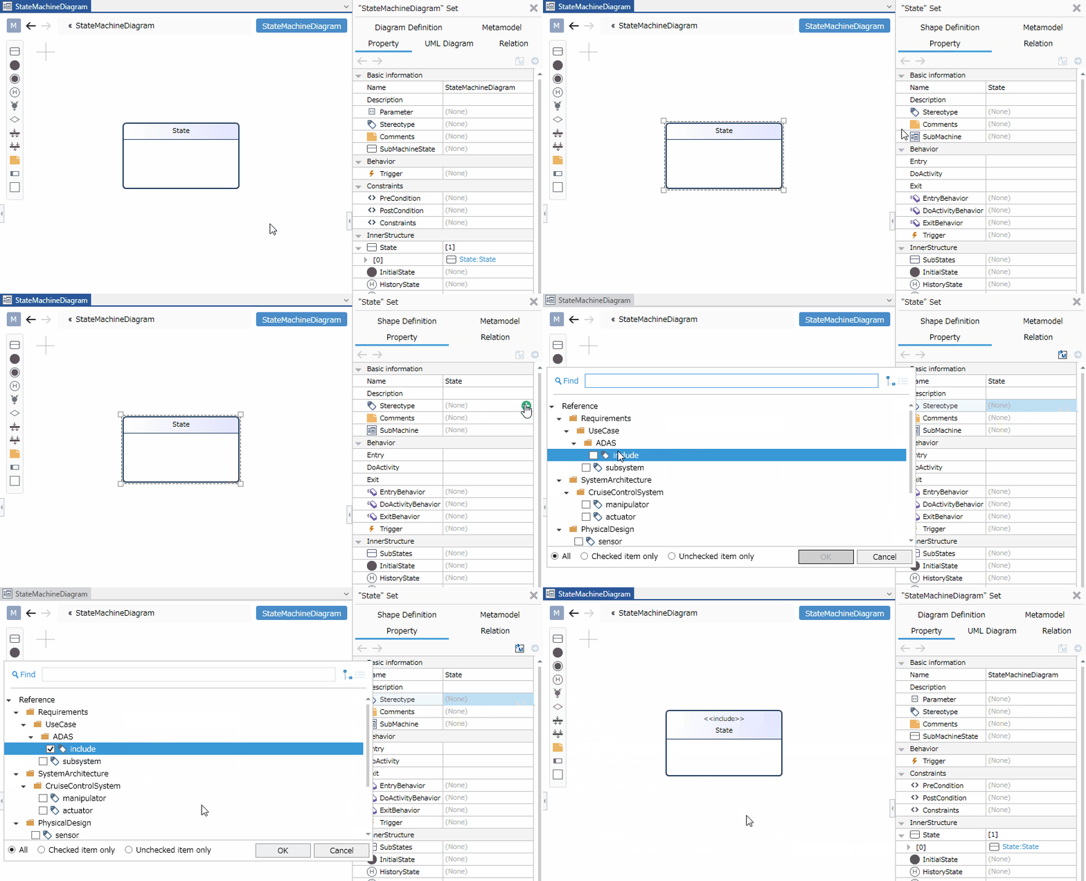
To add a stereotype, follow these steps:
-
Select the state.
-
In the Properties Inspector, click the [Add] button in the [Basic information] > [Stereotype] field to display the options.
-
Select a stereotype and click the [OK] button. The stereotype will be set for the state and displayed on the state machine diagram.
Stereotype options can be defined in the [Detail] view of the package model.
Added stereotypes can be edited from the state machine diagram using the following steps:
-
Double-click the stereotype displayed in the state to enter edit mode.
-
Change the stereotype and confirm the edit. This will be reflected in the state machine diagram, and the state's stereotype will be changed.
Defining Transitions
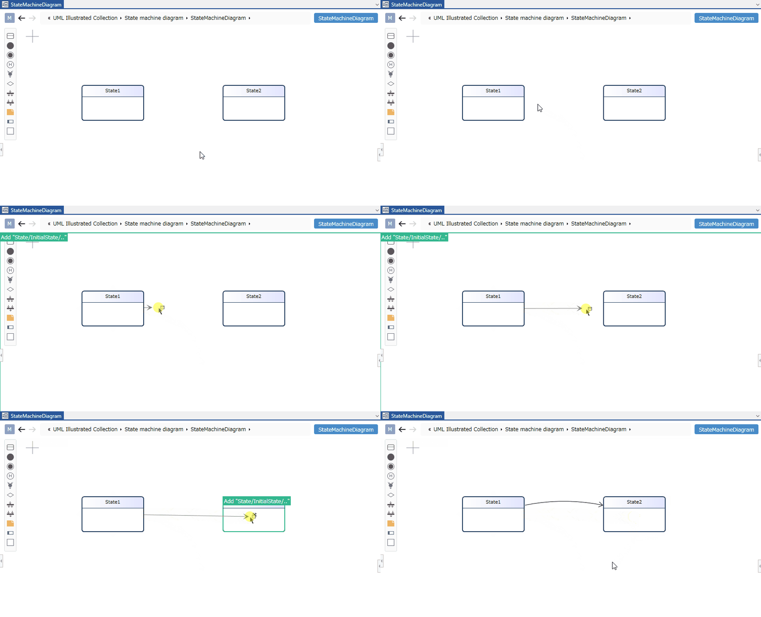
To define transitions between states, follow these steps:
-
Move the pointer over the state that will be the starting point of the transition.
-
Drag the [▲] icons that appear on all four sides of the state and drop them onto the state that will be the ending point of the transition.
Adding a Trigger to a Transition
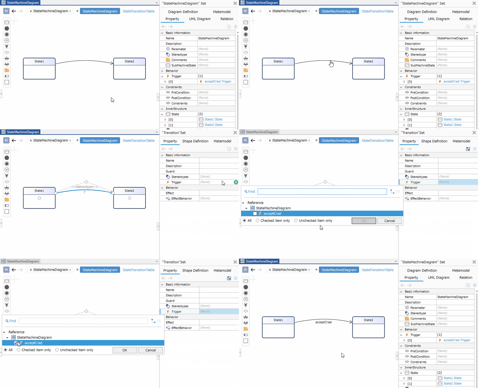
To add a trigger, follow these steps:
-
Select the transition.
-
In the Properties Inspector, click the [Add] button in the [Basic information] > [Trigger] field. The options will appear.
-
Select a trigger and click the [OK] button. The trigger will be set for the transition and displayed on the state machine diagram.
When you enter text in the transition label on the state machine diagram, the text is parsed according to the notation format and reflected in each field value of the transition.
Of course, changing each field value will also be reflected in the text on the diagram.
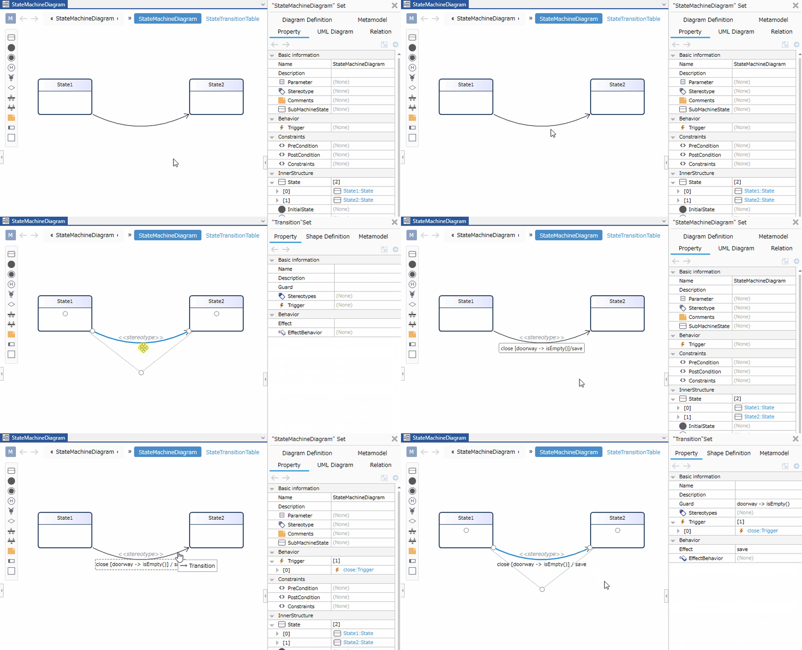
Correspondence between Transition Text Format and Field Values
Transitions are displayed and parsed according to the following format:
- Format:
<Transition> ::= [<List of Triggers>] ['[' <Guard> ']'] ['/' <Effect>] - Notes
<List of Triggers>is displayed in the following format:<List of Triggers> ::= <Trigger>[','<Trigger>]*- Example
Trigger:close
Guard:doorway -> isEmpty()
Effect:closed
In this case, the text will be displayed as follows:
close [doorway -> isEmpty()]/closed
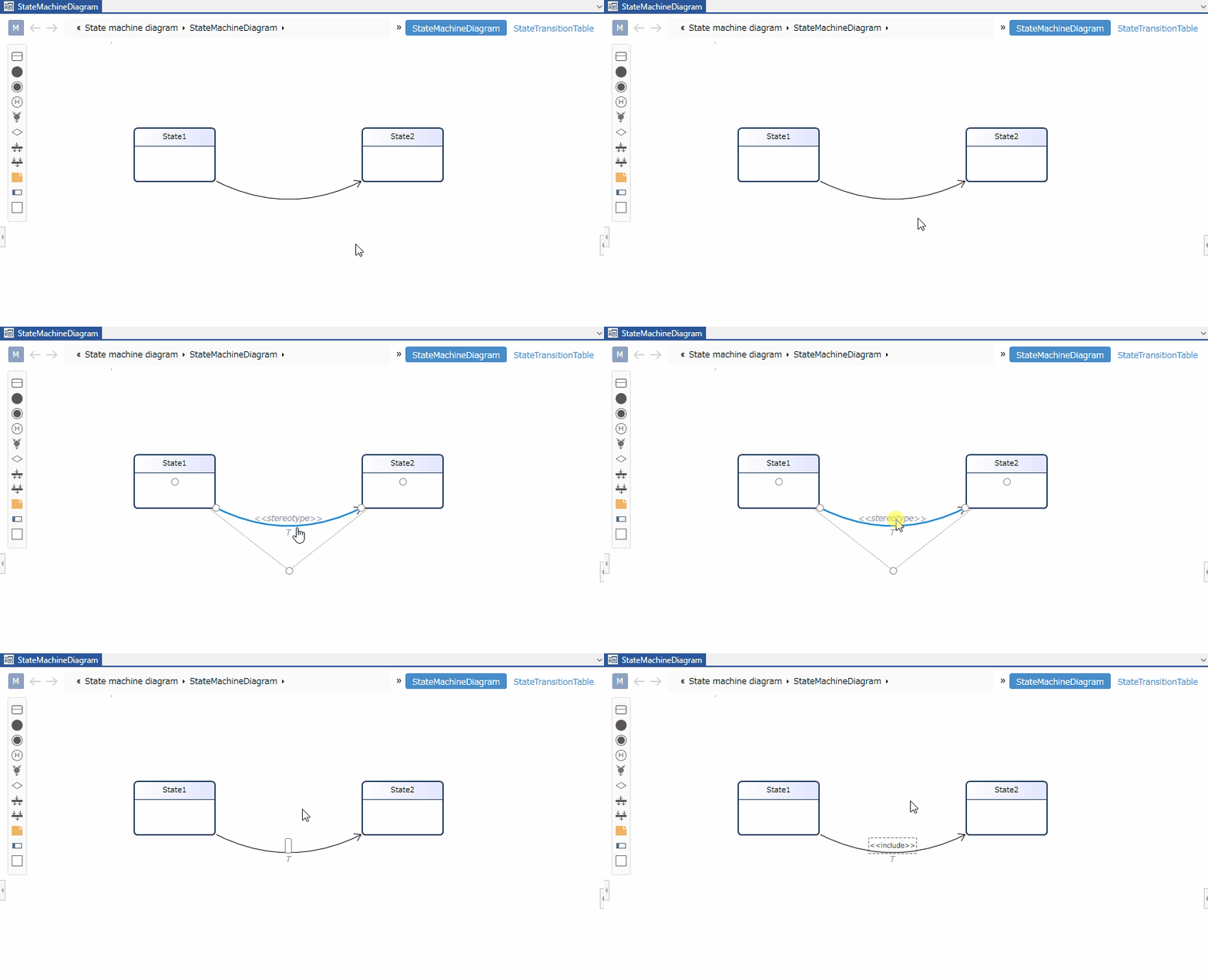
Adding a Stereotype to a Transition
To add a stereotype, follow these steps:
-
Select the transition.
-
Double-click the grayed-out [<<stereotype>>] to enter edit mode.
-
Enter the desired stereotype. The stereotype will appear on the transition in the state machine diagram, and the stereotype will be set for the transition.
Defining Design Information with the State Transition Table
Displaying the State Transition Table
To display the design information of the state machine diagram using the state transition table, follow these steps:
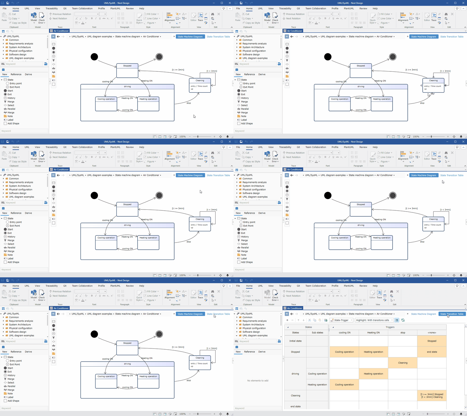
- Switch the editor display to the [State transition table] view according to the following manual.
The state transition table displays the following elements as states:
| Icon | Name |
|---|---|
| Start |
| Entry point |
| State |
| History |
| Selection |
| Parallel |
| Merge |
| Merge |
| Exit Point |
| End |
The states are sorted in the order listed above.
However, they are not sorted between the following elements:
- Selected
- Parallel
- Merged
- Combined
- All states, including substates, are displayed.
- Transitions without a trigger are displayed in the
<None>column. - Selecting a range of merged cells may also select cells outside the range.
- The position of states and triggers (rows and columns) can be switched by selecting [State-Trigger] and [Trigger-State] in the [View Switching] combo box.
Defining States
To define states in the state transition table, follow these steps:
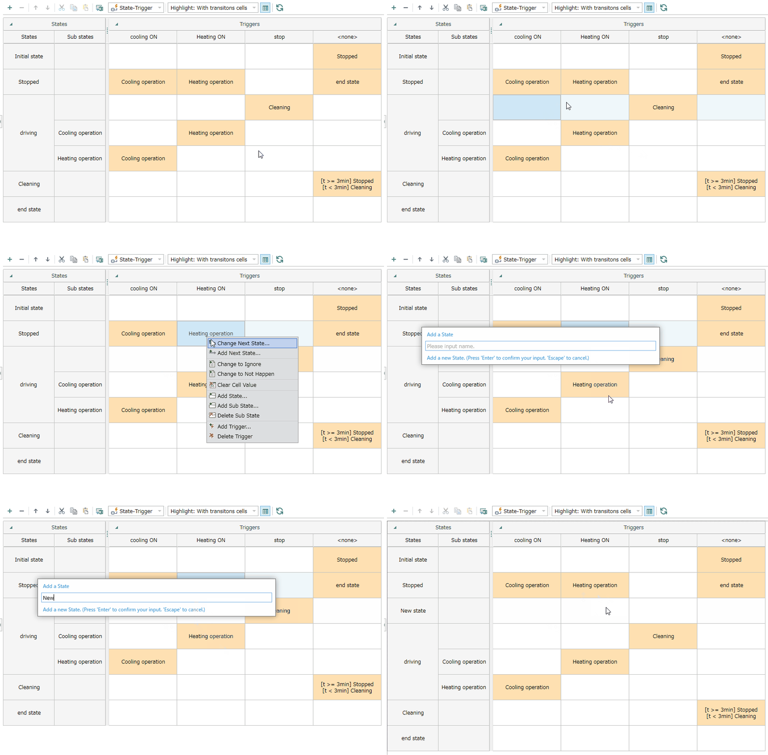
- Select a cell in the State Transition Table and perform one of the following actions:
- Click [Add State (S)...] in the context menu.
- Click the [+] button displayed in the toolbar at the top of the State Transition Table.
-
The [Add State] dialog box will appear. Enter the name of the state you want to add and confirm.
-
A new state with the name entered in step 2 will be added to the row below the selected cell.
-
The state will be added with the same type of element as the elements in the row of the selected cell (Start, Entry Point, State, History, etc.).
-
To add a sub-state, you can add it using the same procedure as above by clicking [Add Sub-State (U)...] in the context menu.
-
To delete a state, select the cell in the row you want to delete and perform one of the following actions:
-
Click [Delete State (D)] in the context menu.
-
Click the [-] button displayed in the toolbar at the top of the State Transition Table.
-
Press the Delete key.
-
If there are no state definitions, you cannot add a state in the [State transition table] view.
Switch to the [State Machine Diagram] view and add a state according to [Define a State](#Define a State).
Defining a Trigger
To define a trigger in the State Transition Table, follow these steps:
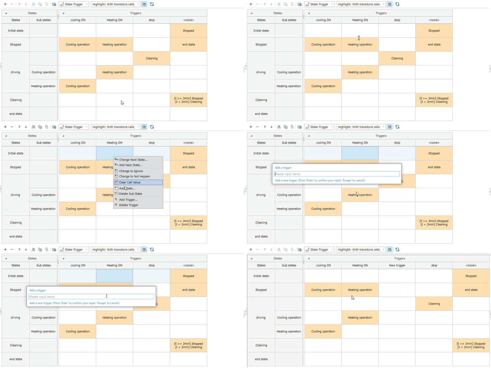
-
Select a cell in the State Transition Table and click [Add Trigger (T)...] in the context menu.
-
The [Add Trigger] dialog box will appear. Enter the name of the trigger you want to add and confirm.
-
A new trigger with the name entered in step 2 will be added to the column to the right of the selected cell.
- To delete a trigger, select the cell in the column you want to delete and delete it from the context menu by selecting [Delete Trigger (E)].
- If there are no trigger definitions in any column, you cannot add triggers in the [State transition table] view.
Switch to the [State Machine Diagram] view and add triggers according to [Define Transitions > Add Triggers to Transitions](#Adding Triggers to Transitions).
Defining Transitions
To define transitions in the state transition table, follow these steps:
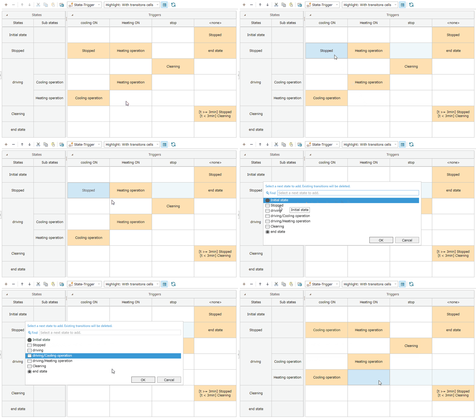
- Select a cell in the state transition table and click [Change Destination (C)...] in the context menu.
-
To add Ignore to a transition, click [Ignore (I)] in the context menu.
-
To add a "NotHappen" status to a transition, click "Make Not Happen" in the context menu.
- Select the destination state according to the dialog box that appears.
- The transition will be added to the selected cell.
- If a transition is already defined in the selected cell, the existing transition will be deleted before adding the new one. Please note that the field values (guards, effects, behaviors, etc.) set for the transition will be deleted.
- To delete a transition, select the cell containing the transition you want to delete and delete it using "Clear Cell Value" in the context menu.
- Cells with defined transitions will be highlighted.
To change the type of highlighted cells, you can change it from the drop-down list in the toolbar at the top of the state transition table.
- This setting is saved per user.
Adding a Transition
To add a transition in the state transition table, follow these steps:
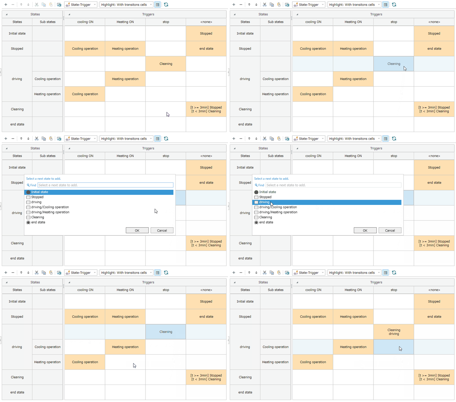
:::note: Procedure
-
Select a cell in the state transition table and click [Add Destination (A)...] in the context menu.
-
Select the destination state according to the dialog box that appears.
-
The transition will be added to the selected cell. Existing transitions will be maintained with this operation.
:::
:::note: Text Notation for Transitions
When you enter text in a transition cell in the state transition table, the text is parsed according to the notation format and reflected in each field value of the transition.
Of course, changing each field value will be reflected in the text on the diagram.
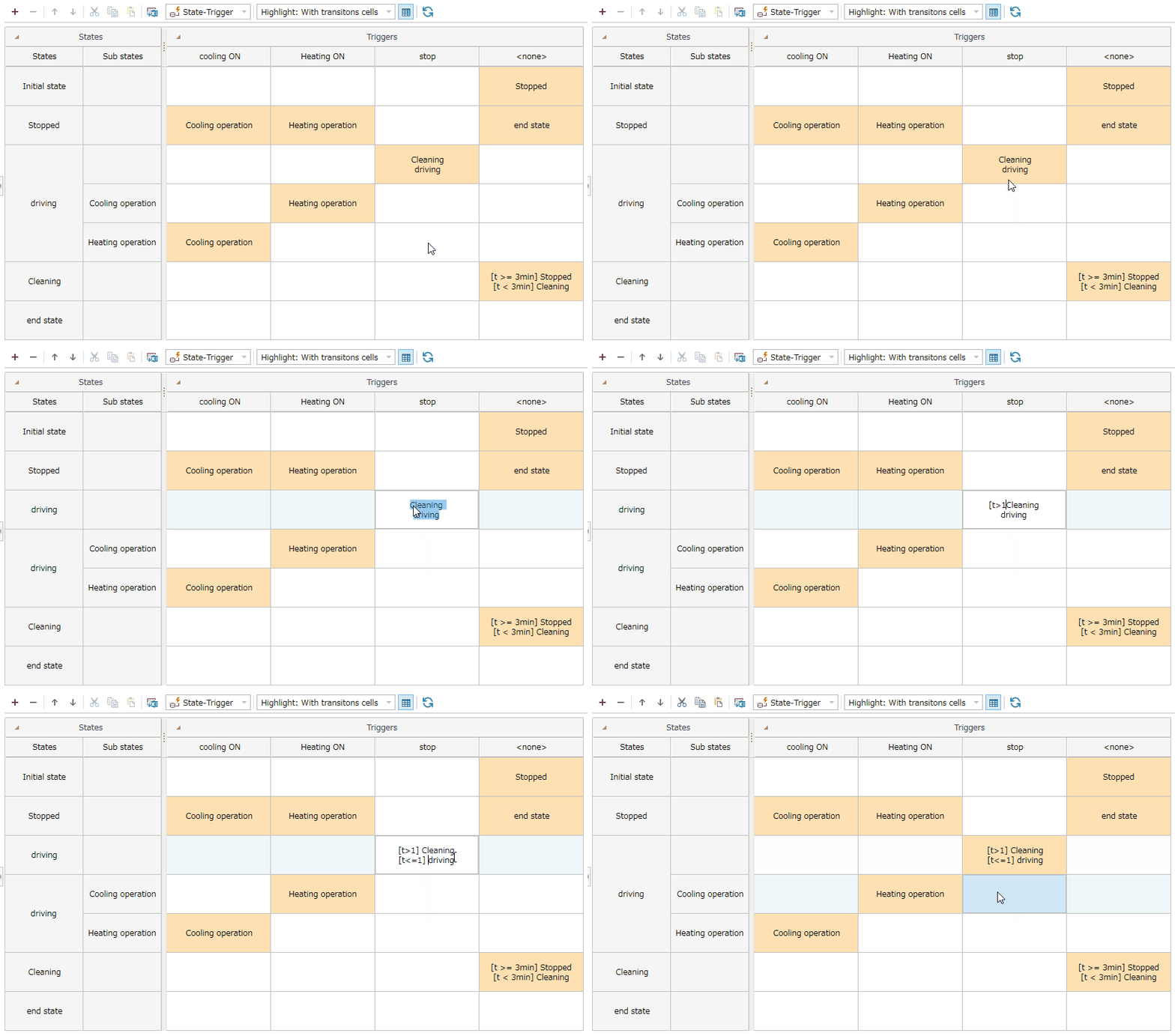
Correspondence between Transition Text Format and Field Values
Transitions are displayed and parsed as text according to the following format:
- Format:
<Text> ::= <Transition> [ <Newline> <Transition> ] *
-
<Transition>is displayed in the following format: -
<Transition> ::= ['['<Guard>']'] <Name of Destination State> -
Example: If one trigger has two conditional transitions, the text will be displayed as follows:
-
Transition 1:
-
Name of destination state:
Cleaning -
Guard:
t>1 -
Transition 2:
-
Name of destination state:
Running -
Guard:
t<=1 -
Text display
-
[t>1]Cleaning <newline>[t<=1]Running -
Notes
-
If
<Name of destination state>is not found in the selected state machine diagram, an error will be notified in the [Information Window] > [Output] tab > [State transition table] category.
Please correct as necessary based on the error message. -
If a state is deleted, the
<Transition>that defined that state as<Name of destination state>will also be deleted. -
Depending on the IME being used, if you confirm the string conversion state while editing a cell, the cell editing state will also be confirmed.
To avoid this issue, please switch your IME. We have confirmed that this issue does not occur with Microsoft IME.
:::
Copying and Pasting Transitions
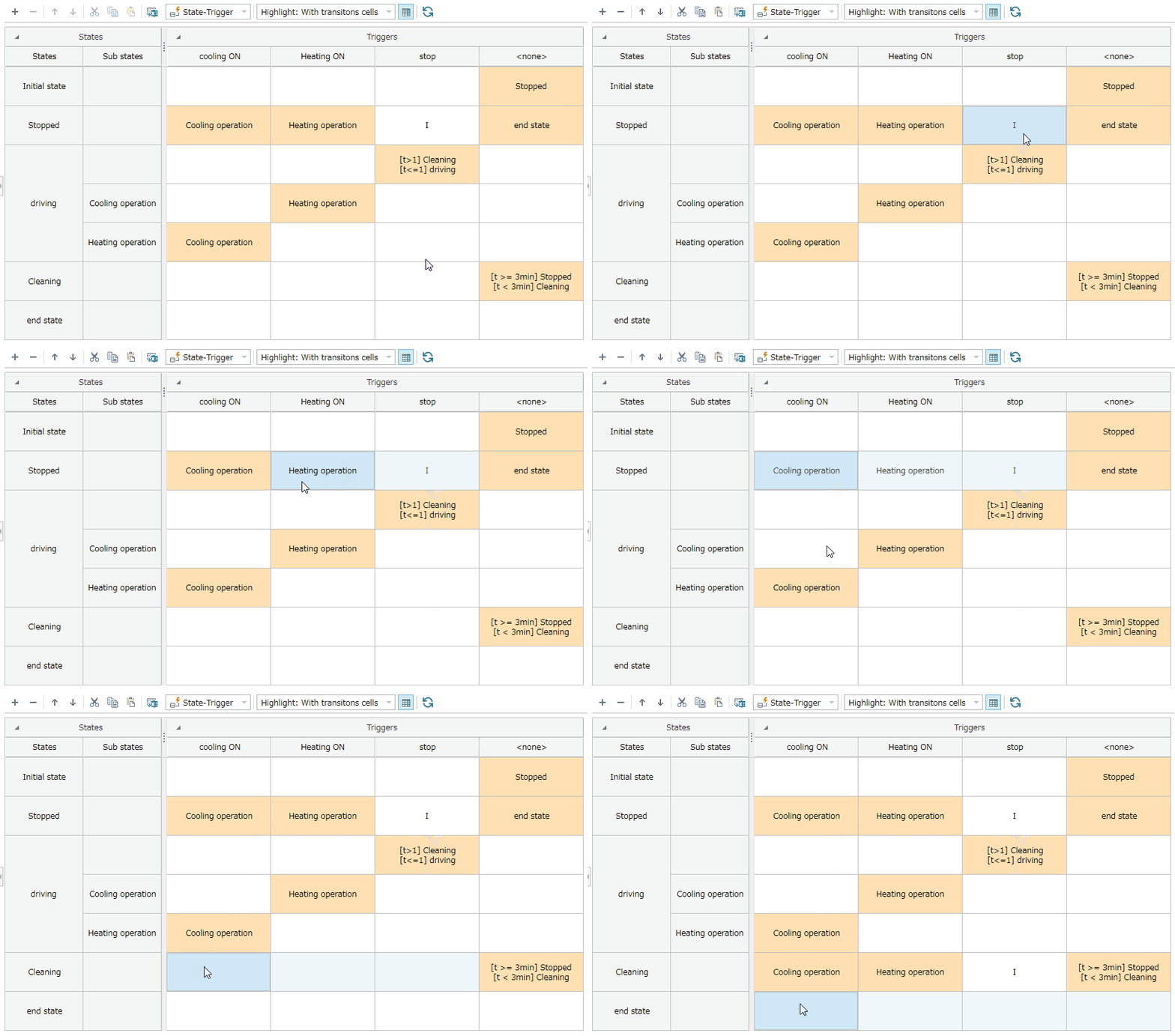
To copy and paste transitions in the state transition table, follow these steps:
-
Select the cell containing the transition you want to copy.
-
Copy the selected cell using ctrl+c.
-
Select the cell where you want to paste the transition and press ctrl+v to paste the copied transition.
When selecting cells representing transitions you want to copy, you can add multiple cells to your selection by holding down the Ctrl key while clicking. This allows you to copy and paste those cells all at once.
Checking Transition Details
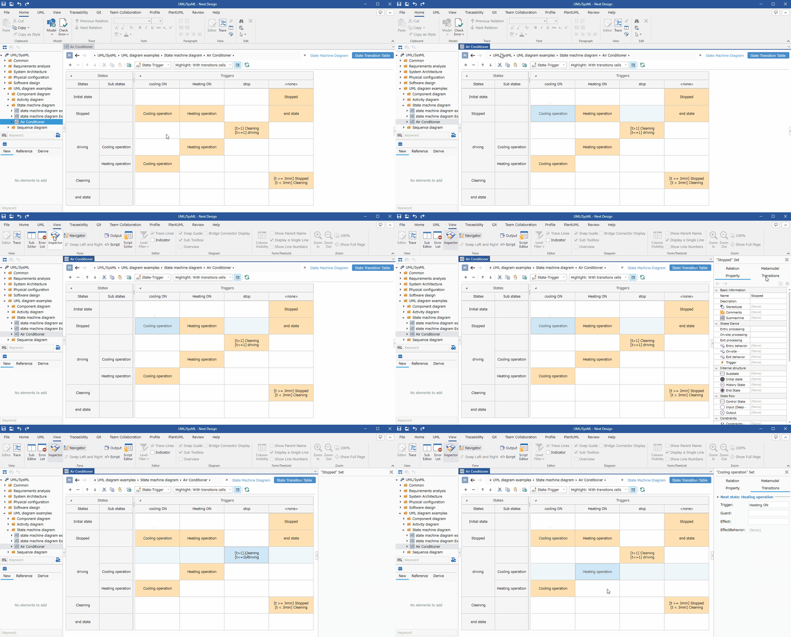
To check transition details in the state transition table, follow these steps:
-
Select the cell in the row representing the state you want to check.
-
Click [View] > [Pane] > [Inspector] on the ribbon to display the Inspector.
-
Confirm that [Transition] is selected in the tab at the top of the Inspector, or click to select it.
-
The Inspector will display the transitions associated with the selected cell's row state and its fields.
The state transition table allows you to view detailed information about the following transitions.
| Field Name | Description |
|---|---|
| Trigger | Name of the trigger referenced by the transition |
| Guard | Guard for the transition |
| Effect | Effect of the transition |
| Transition behavior | Name of the transition behavior owned by the transition |
- Changing the text boxes for triggers and transition behavior will change the names of the owning/referenced models.
Please note that this does not mean that the owning/referenced models are swapped.
Setting the display content
You can display only the information you are interested in in the state transition table without changing the model.
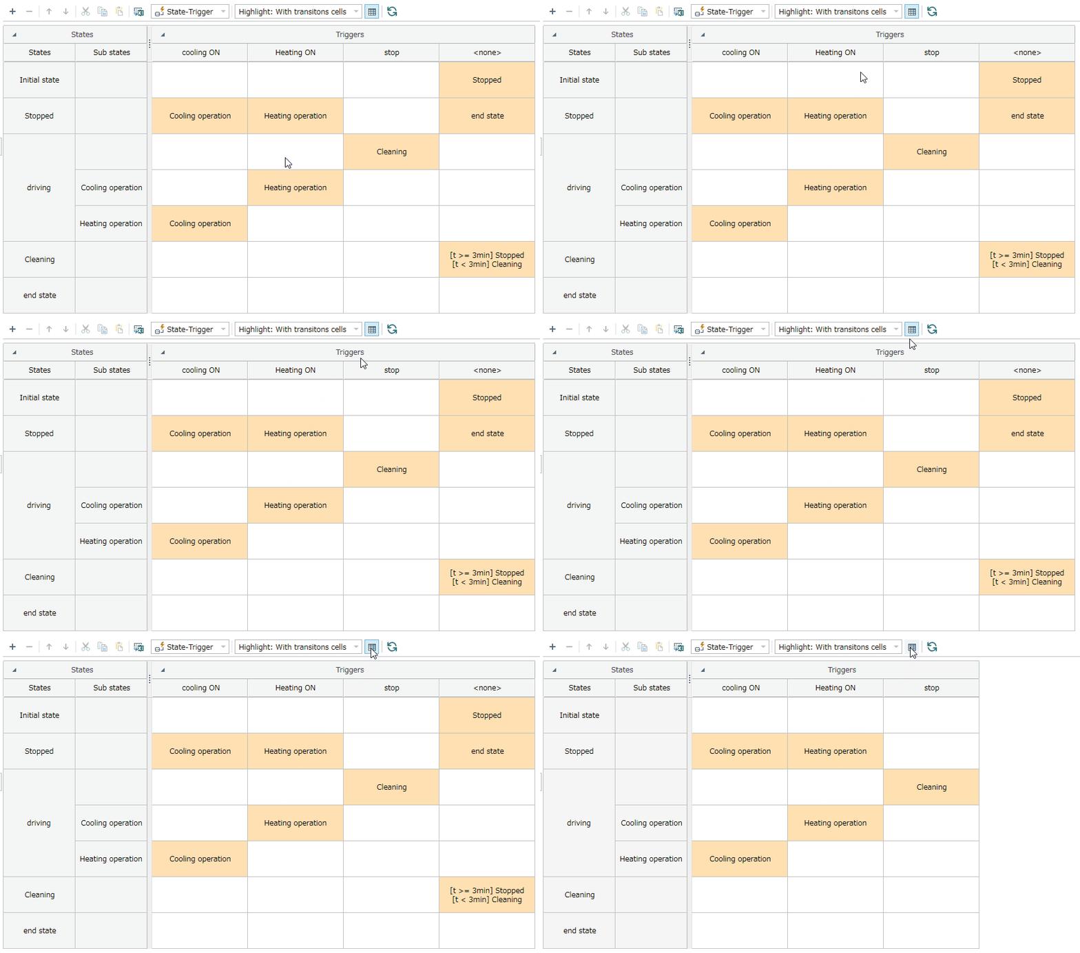
To hide transitions for which no trigger is defined, follow these steps:
:::note: Instructions
-
Click the [Show No Triggers] button on the toolbar at the top of the state transition table.
-
Transitions in the Trigger<None> column will be hidden.
:::
- This setting is saved per user.
Exporting to Excel
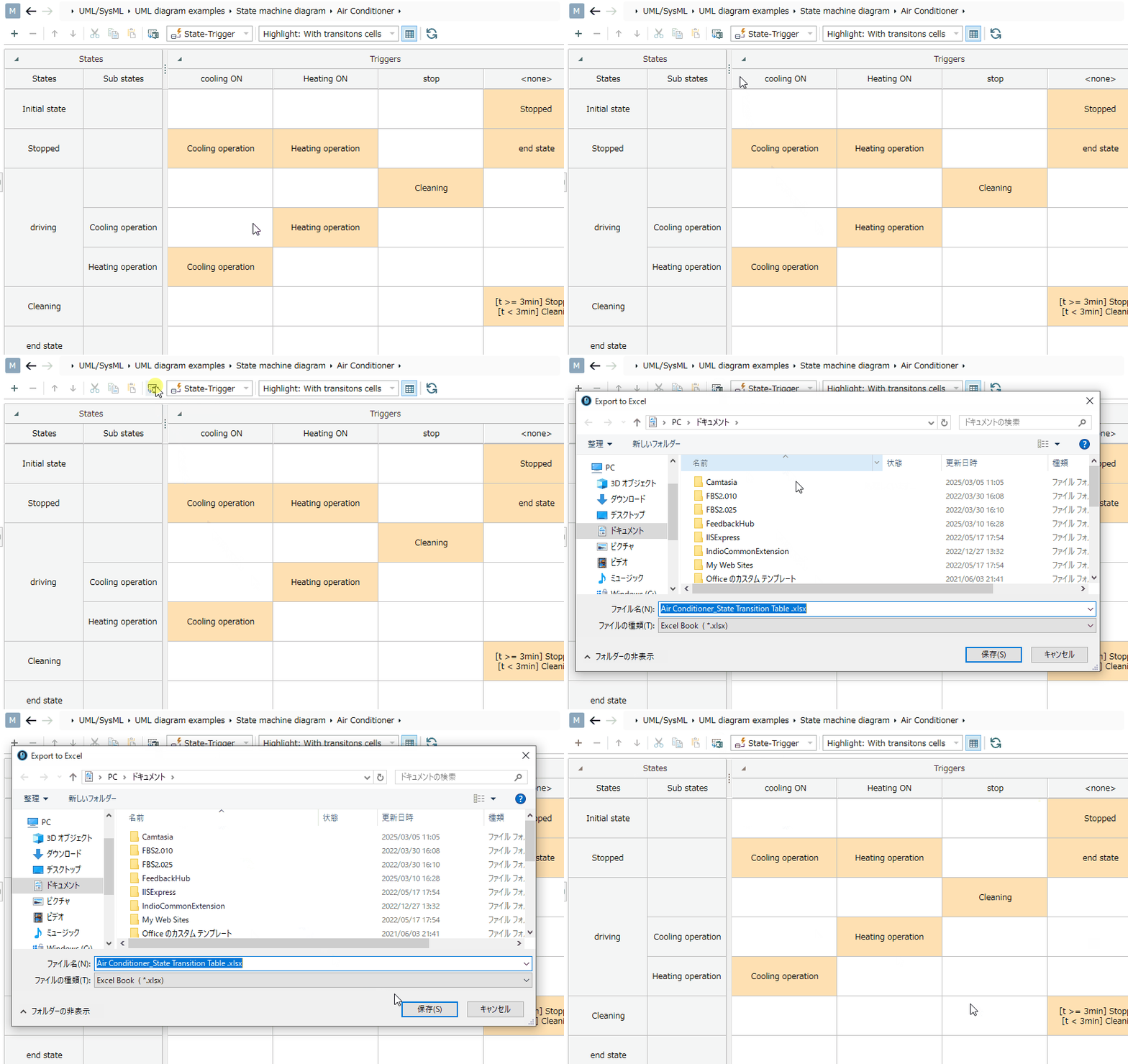
To export the state transition table to Excel, follow these steps:
:::note: Instructions
-
Click the [Export to Excel] button on the toolbar at the top of the state transition table.
-
In the [Export to Excel] dialog box, select the destination for the Excel file and save it.
:::
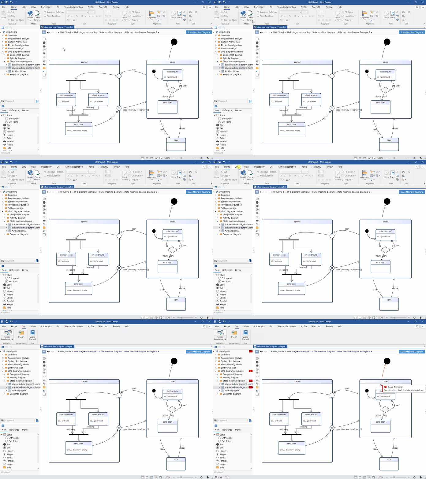
Validating the Model
The following is validated in a state machine diagram:
- Whether there are any transitions ending at the initial state
- Whether there are any transitions starting at the final state
To validate the model, follow these steps:
-
From the ribbon, execute [UML] > [Validation] > [Check Consistency].
-
If invalid transitions are detected for all models under the project, an error message will be displayed.
Clicking the [Home] > [Model] > [Check Error] button on the ribbon performs validation for all models in addition to the standard validation.
Also, when a new transition is added to the state machine diagram, the added transition is checked in real time.
Setting Display Content
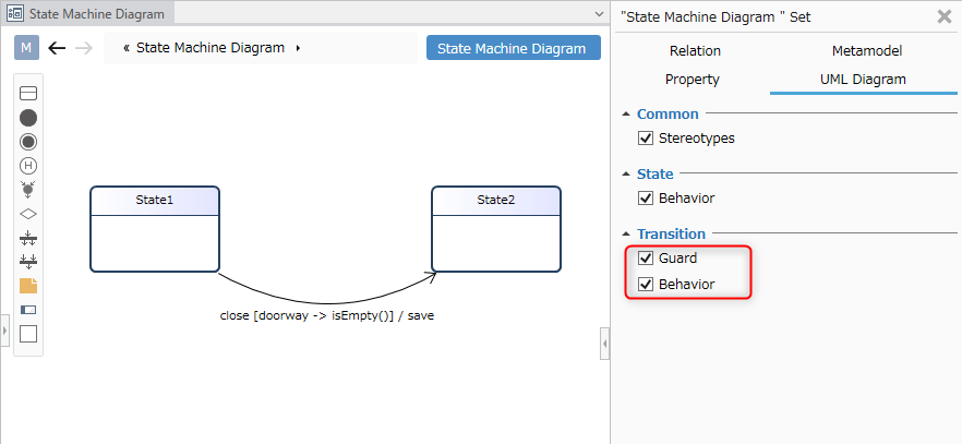
You can display only the information you are interested in in the state machine diagram without changing the model.
To set the display content of transition behavior, follow these steps:
-
Display the state machine diagram whose display you want to switch.
-
In the Inspector, toggle the checkbox in the [Transition] group of the [UML Diagram] tab.
The following elements can be switched in a state machine diagram:
| Category | Element |
|---|---|
| Common | Stereotype |
| State | Behavior |
| Transition | Guard |
| Shake Dance |
Restrictions
-
If the display scale in the display settings is set to a value greater than 100%, some of the text in the state transition table cells may be cut off.
-
Parallel states cannot be defined.
-
State regions, list displays, and functions cannot be represented or described.
-
Subsystem states are represented with an underline in the state name, unlike the UML standard notation.
-
Underlining cannot be specified in the state name style. When the state is a submachine, an underline is automatically displayed.
-
When toggling the checkbox in the [Transition] group of the [UML Diagram] tab in the Inspector, the display content is not updated immediately. The display content will be updated by displaying another view once and then displaying the state machine diagram again.
-
The following values are used as reserved words. Using this in state names or guards may lead to misinterpretation.
- Strings containing "[" (opening bracket) and "]" (closing bracket)
- I
- N
-
In the State Transition Table view, display and editing may take time if the number of elements in rows and columns is large. Please use hierarchical structures as needed.
-
When performing clipboard operations (copy, cut, paste) in the State Transition Table view, please use the buttons on the toolbar at the top of the State Transition Table, not the [Home] > [Clipboard] button on the ribbon.
-
Even if you execute [Export to Excel] on the State Transition Table view toolbar, the alignment (direction) of cell contents and cell colors will not be reflected in the output Excel file.
-
Only state transition tables where states are rows and triggers are columns are supported. State transition tables where triggers are rows and states are columns, or state transition tables where the previous state is a row and the next state is a column, are not supported.
-
Notes cannot be set for columns without triggers in the State Transition Table view.
-
If you add or delete states or triggers in a view other than the state transition table while it is displayed, the state transition table will not update immediately. The update will occur when you click [Refresh] on the toolbar or when you display another view and then display the state transition table again.
-
If you edit the attributes (triggers, guards) of a newly added transition in a view other than the state transition table while it is displayed, the state transition table will not update immediately. The update will occur when you click [Refresh] on the toolbar or when you display another view and then display the state transition table again.
-
Immediately after adding a state using the [+] button on the state transition table toolbar, you cannot create a transition to that state by editing the cell text. Please use [Change Destination (C)...] in the cell's context menu.
-
If there is a custom class model derived from the metamodel related to the state machine diagram (state machine diagram, state base, trigger), the state transition table view may not display correctly.
-
If there is an unloaded model among the child elements of the state machine diagram, the state transition table view may not display correctly.
-
State names in the state transition table view must be unique. Using the same name for multiple states may lead to misidentification of transitions.
-
Assigning multiple triggers to a transition may also lead to misidentification of transitions in the state transition table view.
-
For future advanced feature enhancements, you can add state transition table view definitions from the context menus and ribbons of various navigators.
-
This is a reserved feature; please do not use it.