Modeling Guide
Overview
This page explains the operations for using FT diagrams in the following order:
- Placing the FTA model
- Creating the FT diagram
- Designing countermeasures for causes
- Dividing deeply nested FT diagrams
Placing the FTA Model
To create an FT diagram, you must first place the FTA model.
To place the FTA model, follow these steps:
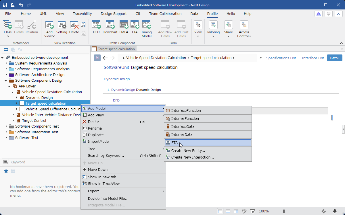
- In the [Model Navigator], select the model on which you want to place the FTA model, and click [Add Model] > [FTA] in the context menu.
- [FTA] will be placed as a child element of the selected model.
Creating an FT Diagram
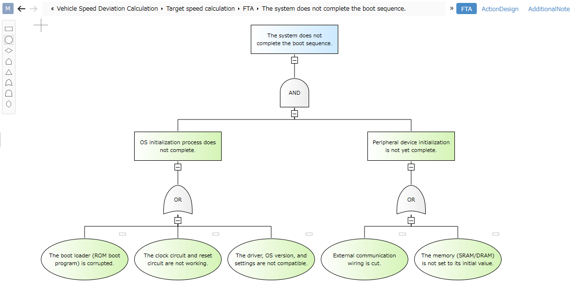
To create an FT diagram like the one shown below, follow these steps:
Placing the Top Event
To create an FT diagram, you must first place the top event.
To place the top event, follow these steps:
-
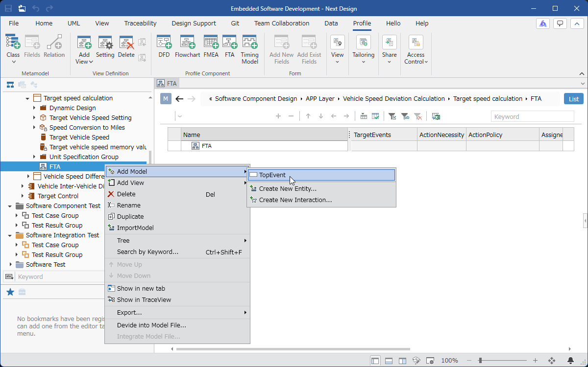
Select the FTA model in the [Model Navigator] and click [Add Model] > [Top Event] in the context menu.
-
[Top Event] will be placed as a child element of the selected model.
The top event model has multiple views defined. The defined views are as follows:
| View Name | Features |
|---|---|
| FTA | Create an FT diagram. |
| Treatment Design | Design the treatment for the cause identified in the FT diagram. |
| Additional Information | Describe the explanation for the top event. |
Implementing FTA for the Top Event
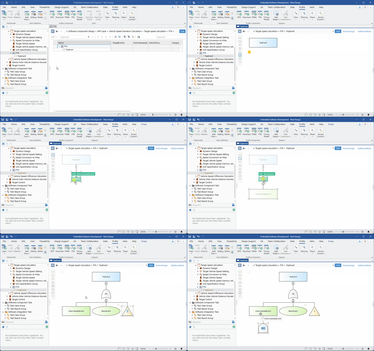
To implement FTA for the top event, follow these steps:
-
Select [Top Event] in the [Model Navigator] and switch to the [FTA] view.
-
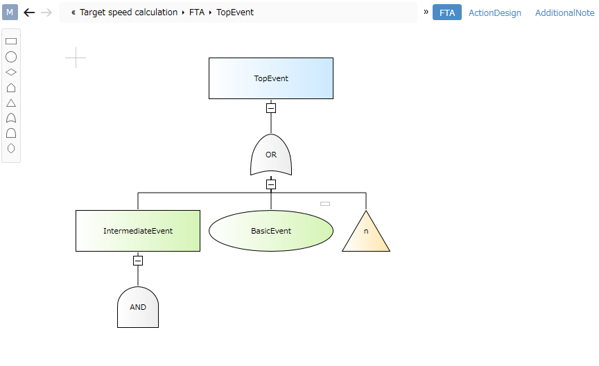
Drag and drop events (intermediate events/basic events, etc.) and logic gates (AND/OR, etc.) from the [Tool Box].
The following elements displayed in the tool box can be added to the FT diagram.
| Icon | Name |
|---|---|
 | Intermediate Event |
 | Basic Event |
 | Undeveloped Event |
 | Normal Event |
 | Concatenation Symbol |
 | OR Gate |
 | AND Gate |
 | Constraint Gate |
Setting the Linked Event for the Link Symbol
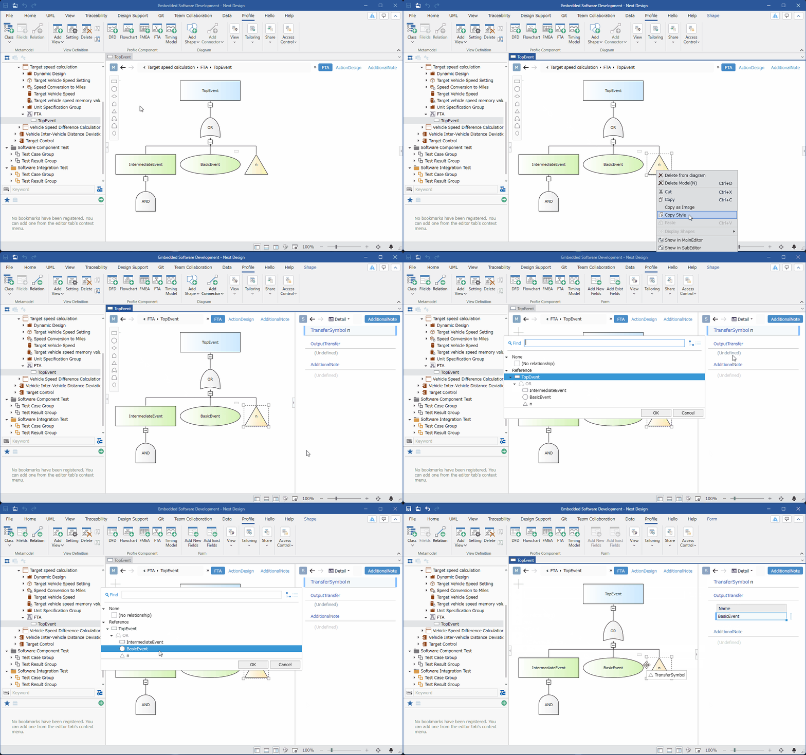
To set the linked event for the link symbol, follow these steps:
-
Select the link symbol element and click [Show SelectedItem at SubEditor] in the context menu.
-
Click [Add Event Symbol] in the [Linked Destination] field of the [Sub Editor] to set the linked event.
Designing Actions for Causes
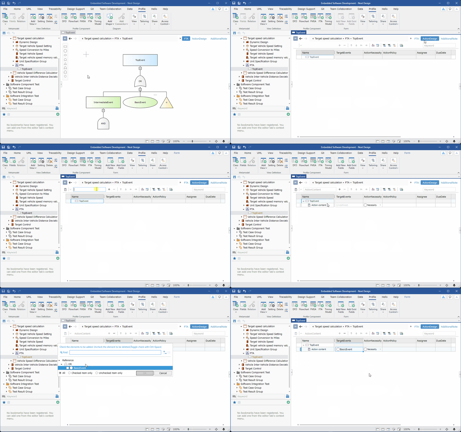
To design actions for causes identified in the FT diagram, follow these steps:
:::note: Operating Procedure
-
Select [Top Event] in the [Model Navigator] and switch to the [Treatment Design] view.
-
Enter the treatment details in the text box on the toolbar at the top of the tree grid and press the Enter key. It will be added to the end of the [Top Event]'s children.
-
Click [Edit] in the [Target Item] column of the treatment details and check the checkbox for the event that the treatment details target.
-
Enter the necessary information in each column.
:::
Dividing a Deeply Hierarchical FT Diagram
You can divide a deeply hierarchical FT diagram by adding a top event and setting the added top event as a linking symbol.
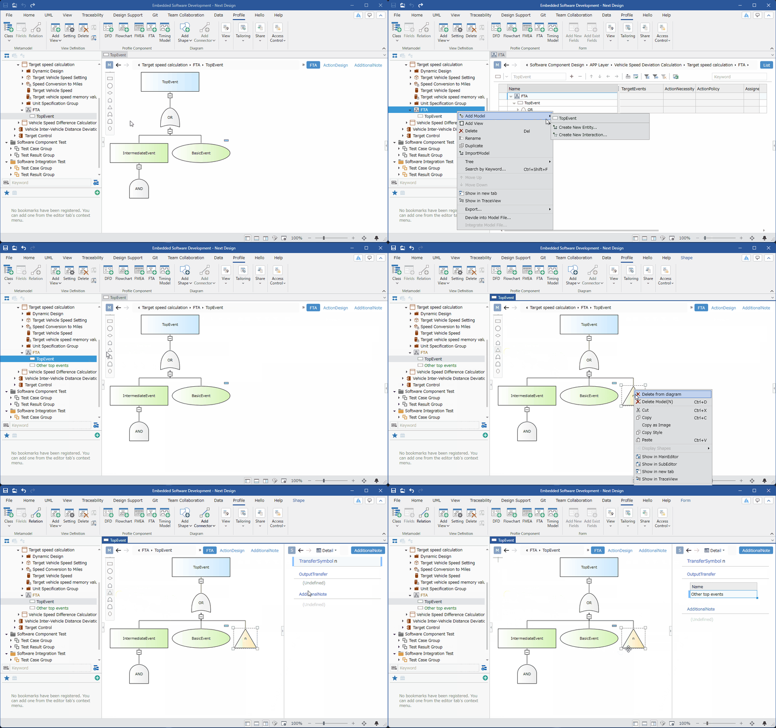
To divide an FT diagram, follow these steps:
-
Select the FTA model in the [Model Navigator] and click [Add Model] > [Top Event] in the context menu.
-
Display the [FTA] view and drag and drop the [Connecting Symbol] from the [Tool Box].
-
Select the connecting symbol element and click [Show SelectedItem at SubEditor] in the context menu.
-
Click [Add Event Symbol] in the [Connecting Destination] field of the sub-editor and set the top event added in step 1.
The split FT diagram can be displayed from the connecting symbol element using the following steps.
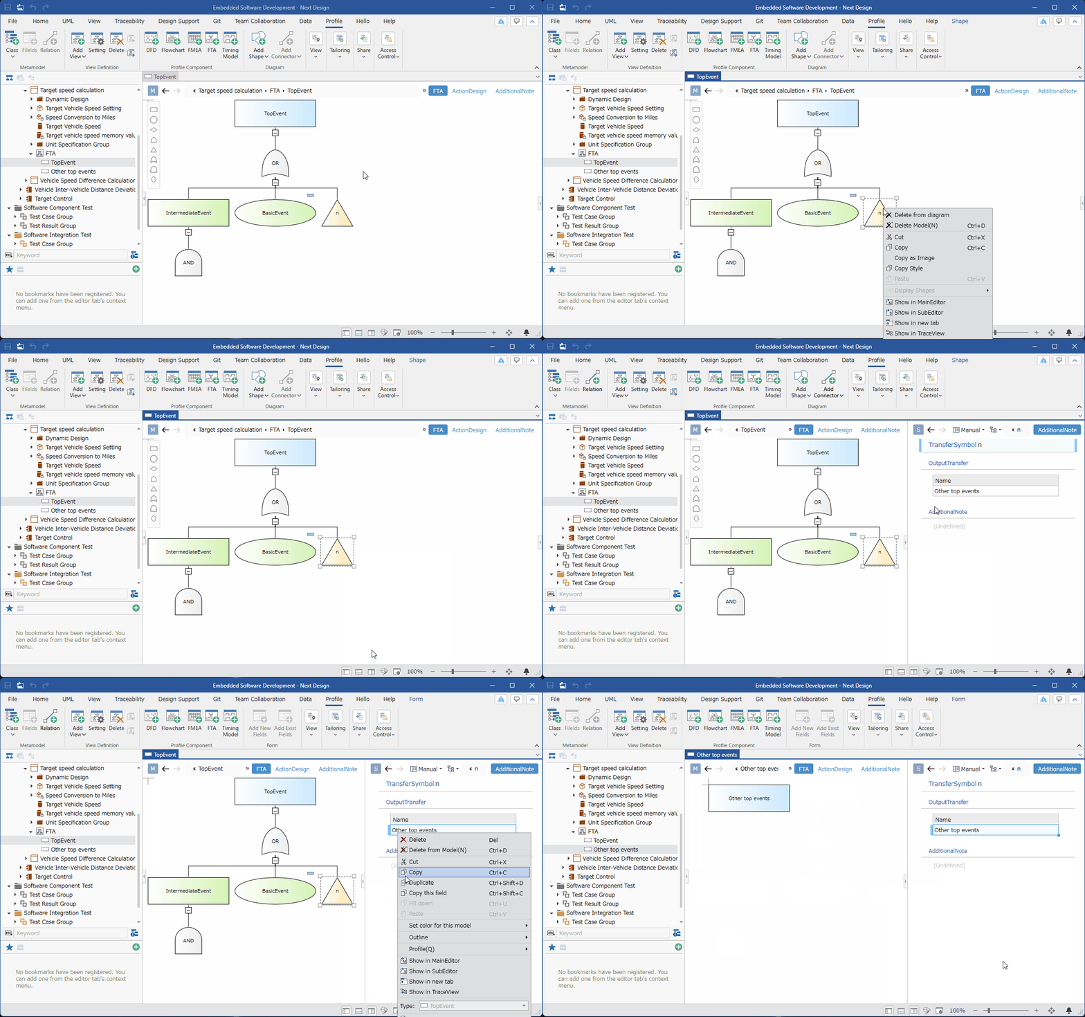
Operational Procedure
-
Select the element of the linking symbol and click [Show SelectedItem at SubEditor] in the context menu.
-
Select the element in the [Linked To] field of the subeditor and click one of the following in the context menu:
-
[Show in Main Editor]
-
[Show SelectedItem at SubEditor]
-
[Show in new tab]