define diagram view
Overview
A profile can define the structure of a model as a metamodel and the representation of the model as a view. The definition of the diagram view defines the following items as the representation format of the model.
- entity shape
- Relation lines (connectors) between entities
Below, let's define a diagram view that allows us to edit the [UseCase Model] in UML UseCase diagram format by following the steps below.
- Add a view to the [use case model] defined in the meta model
- Add a shape for each Actor and Use case entity defined in the metamodel
- Added connectors for reference relationships between [Actor] and [Use case] defined in the metamodel.
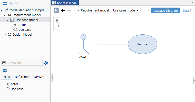
Image of diagram view to define
1. Add a view to the model
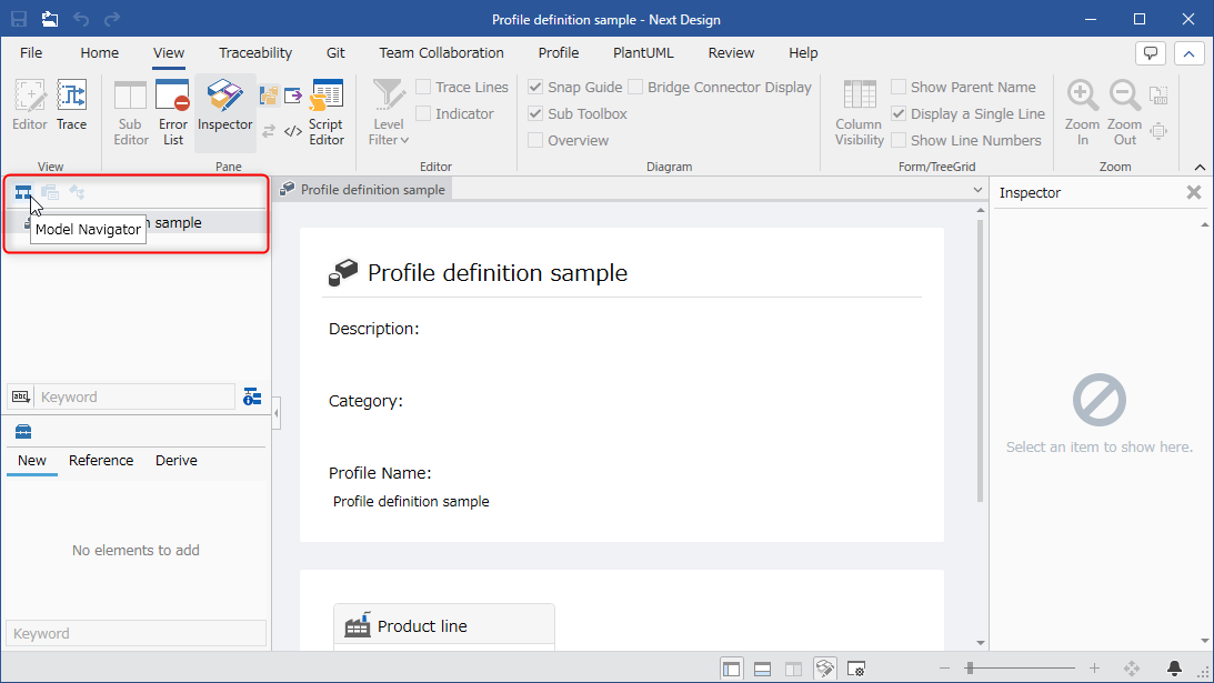
Switch to model edit screen
View definition is done on the model edit screen used for modeling. First, select [Model Navigator] from the selector at the top of the navigator to switch to the model editing screen.
add use case model for view definition
To start the view definition, you need to add one model for the view definition in the model navigator. Follow the steps below to add a use case model for view definition.
- Right-click [Profile definition sample] displayed at the top of the model navigator, and Click Add Model > Requirement Model from the context menu to Add [Requirement Model] directly under the project.
- Right-click on the added Requirement model and select Click [Add Model] > [Use Case Model] from the context menu to Add a use case model for view definition.
- You have now added the Requirement Model > Use Case Model you need to start your view definition.
Add ER diagram view to use case model
To make the Use Case Model editable in Use Case Diagram format, Add the ER diagram to the Use Case Model view as follows:
- Select Use Case Models in the Model Navigator.
- Click Profile > View Definition > Add View from the ribbon and click ER in the diagram to The New Diagram dialog is displayed.
- Enter [Usecase Diagram] as the display name and press the [OK] button to add view options to the upper right of the editor editing area.
2. Add Shape by Entities
To be able to add models to the added diagram view, add a shape to the view, Assign an entity defined in the metamodel.
Here, we will walk you through adding the following shapes and assigning them entities so that you can add an Actor and a Use case to your view.
| Types of Shapes | Entities | Diagrams |
|---|---|---|
| [With Label] Shape | [Actor] | UML/SysML Shape > Actor |
| [Title Only Shape] Shape | [Use case] | UML/SysML Shape > Use Case |
- Click Profile > Diagram > Add Shape from the ribbon and click the type of shape you want to add.
- Select the entity to assign in the Target Field of the New Shape dialog.
- Continue to set the following items in the dialog.
- Select the shape of the shape in [Diagram] of [Style].
- In [Title] and [Body] of [Text], select the field to be displayed on the shape and the type of [Alignment].
- When you press the [OK] button in the dialog, the corresponding icon is added to the toolbox and can be added to the view.
3. Add a connector for reference relationships between entities
In order to be able to connect the model components on the ER diagram view with association lines, add a connector to the view, Assign associations defined in the metamodel.
Here, the relationship line corresponding to the reference relationship of [Actor] and [Use case] linked in the meta model is I will explain the procedure to make it possible to connect on the ER diagram view.
- Add [Actor] and [Use case] on the ER diagram view.
- Hold ctrl and click to select Actor and Use case.
- From the ribbon, click Profile > Diagram > Add Connector, click the ▼ at the bottom, and click Add Connector Exist Reference.
- In the New ConnectorShape dialog, for Relationship Class, select Actor to UseCase Reference as the relationship to assign, and Click the [OK] button.
- Now that you've added a connector, you can connect those entities on your diagram.
- A connector must be defined for each association defined in the metamodel.