Deriving a model
Overview
Next Design not only allows you to handle various models related to the software you are designing in a single project, but also automatically records trace information between models by creating a new model using an existing model as input, eliminating the need to add trace information later.
The design act of creating a new model using an existing model as input is called model derivation.
Below, we will explain the metamodel definition and model derivation required for model derivation in the following order.
- Define a derivation relationship in the metamodel so that a component structure model can be derived from a use case model.
- Derive a component configuration model using a use case model as input.
- Add trace information between existing models. Image of derivation relationship definition
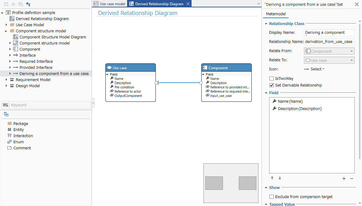
Image of model derivation and tracing
1. Define a derivation relationship in the metamodel
To derive a component structure model from a use case model or to be able to connect trace lines, define a derivation relationship between entities using the following procedure.
- Define the metamodel and view of the [Component Structure Model] to be derived.
- Define the derivation relationship between the entities of the [Use Case Model] and [Component Structure Model].
1.1 Define the metamodel and view of the component structure model.
Define the metamodel of the [Component Structure Model] to be derived with reference to the following class diagram.
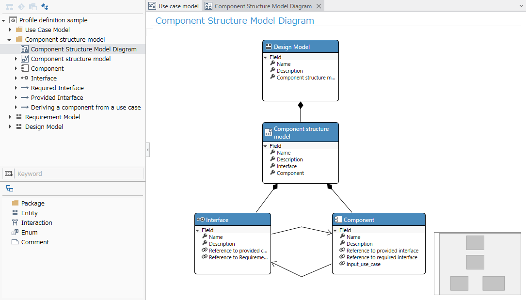
- For the procedure, refer to the above Quick Start > Profile Definition > Define Metamodel.
Define the diagram view of the [Component Structure Model] with reference to the following screen image.
- Please refer to the procedure in Quick Start > Profile Definition > Define Diagram View mentioned above.
1.2 Define derived association between use case and component
To define derived association between entities in [Use Case Model] and [Component Structure Model], use a class diagram to define it, just like defining reference association.
Here, we will create a new class diagram to define the derived association and illustrate only the entities to be associated.
| Entity to be derived | Entity to be derived from |
|---|---|
| Component Structure Model > Component | Use Case Model > Use Case |
- Add a class diagram to the profile and enter [Derived Relationship Diagram] as the name.
- Add an existing entity to be connected with the derivation relationship from [Profile Navigator] to the class diagram.
- Connect the derivation relationship from the derived entity to the derived entity.
- By defining the derivation relationship, you can derive the model and add trace lines.
Now you have defined the metamodel of [Use Case Model] with [Actor] and [Use case] as components, and the metamodel of [Component Structure Model] that can be derived.
2. Derive a component from a use case
To derive a new model by inputting an existing model and combining it with trace information, follow these steps:
-
Display two models side by side
-
Create a model using the components of the input model
2.1 Display two models side by side
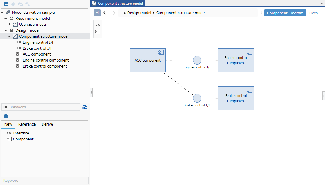
Add a model
As with adding a [Use case model], add the [Component structure model] to be edited from the Model Navigator.
- Model to be edited: [Modeling sample] > [Design model] > [Component structure model]
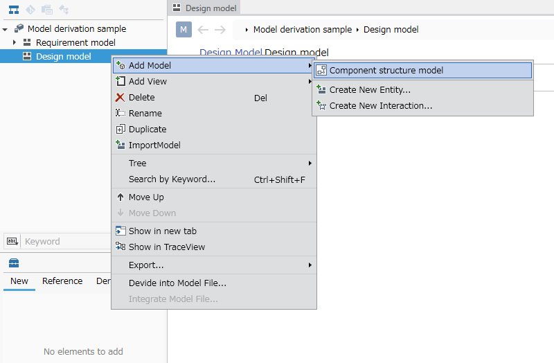
- First, right-click the project displayed at the top of the Model Navigator, and click [Add Model] > [Design model] from the context menu to add a [Design model] to the first level.
- Right-click the added [Design Model], and click [Add Model] > [Component Structure Model] from the context menu to add the model to be edited.
- When you add a model in the model navigator, the model is displayed in the main editor and can be edited.
Displaying the model in the sub editor
To display the sub editor on the right side of the screen and display the [Use Case Model] that is the input for model creation, follow the steps below.
- Click [View] > [Pane] > [Sub Editor] on the ribbon.
- Select [Input (Deep Blue)] from the [Display Mode] pull-down list at the top of the sub editor.
- Select [Use Case Model] from the pull-down list that appears to the right of it.
- To swap the positions of the sub-editor and main editor, click [View] > [Pane] > [Swap Left and Right] on the ribbon.
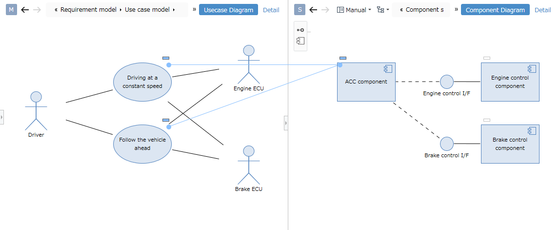
2.2 Create a model using components of an input model
To derive a new model using an existing model as input and trace information, drag and drop the components of the input model as follows.
- Move the pointer over a component of an existing model and drag the [+] icon displayed in the upper right.
- When you drop it on the model to which you want to derive, the component is added to the model and a trace line is added to show the derivation relationship between the models.
3. Add trace information between existing models
To add trace information between existing model components, drop it on the [○] icon displayed in the upper left of the model component to which you want to drag.
- Move the pointer over a component of an existing model and drag the [+] icon displayed in the upper right.
- Drop it onto the [○] icon displayed in the upper left of the existing model to which you want to attach a derived association.
- When you drop it, a trace line representing the derived association is added between the existing model components.