Define metamodel
Overview
A metamodel defines the structure and relationships of entities.
By defining a metamodel, you can formalize the content to be designed and the constraints to be considered during design.
The following describes the basic steps for creating a new profile and defining a metamodel, using a use case model consisting of actors and use cases.
Image of the metamodel to be defined
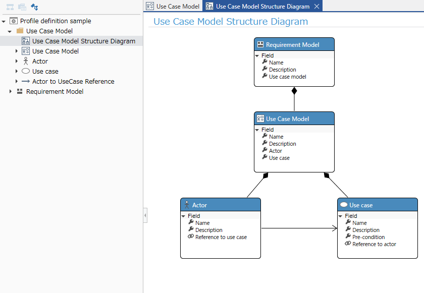 Overall structure of metamodel
Next Design allows you to handle various models related to a product in one project, so the number of models in a project will be large.
For this reason, a hierarchical structure that allows you to roughly classify the types of models directly under the project is useful.
In the following, we will define a metamodel to create a project with the following hierarchical structure.
In this example project, [Requirements Model] and [Design Model] are created directly under the project to roughly classify the model types.
Overall structure of metamodel
Next Design allows you to handle various models related to a product in one project, so the number of models in a project will be large.
For this reason, a hierarchical structure that allows you to roughly classify the types of models directly under the project is useful.
In the following, we will define a metamodel to create a project with the following hierarchical structure.
In this example project, [Requirements Model] and [Design Model] are created directly under the project to roughly classify the model types.

Also, if you expand the scope of the project, the number of components of the metamodel defined in the profile will also increase. For this reason, it is useful to create a package for each model type and classify the components of the metamodel. This makes it easier to get an overview of the overall structure of the metamodel.
In the following, we will define the metamodel by creating a [UseCase Model] package as follows. In this profile example, we create a [UseCase Model] package directly under the profile root to classify the components of the metamodel.

Preparation
Understanding the screen layout
When defining a metamodel, the Profile Navigator is displayed on the left, the class diagram in the center, and the Inspector on the right.
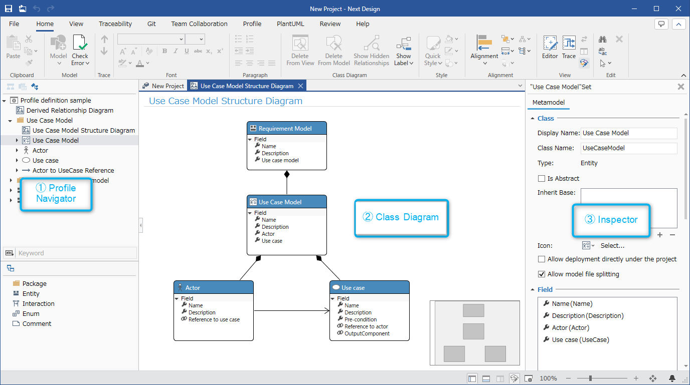
To open a class diagram in the center, double-click the class diagram you want to open in the Profile Navigator. To close a class diagram, click the [x] displayed on the class diagram tab.
- Unlike the Model Editor, the display of the class diagram does not change even if you click a tree node in the Profile Navigator to change the selected node.
- To display a different class diagram, double-click the class diagram you want to display to open it.
Below, let's define a metamodel for a use case model using the following procedure.
- Add a use case model to a profile
- Define the structure of the use case model
1. Add a use case model to a profile
To add a meta model of a use case model to a profile, follow the steps below.
- Create a project for a new profile
- Configure the profile and add the [Use Case Model] entity
- Prepare a class diagram to define the meta model of the [Use Case Model]
1.1 Create a new project
Create a project for a new profile
To create a project for a new profile, create a new project by following the steps below.
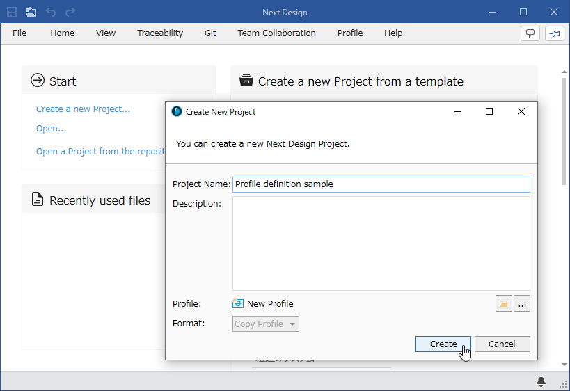
- Start Next Design and click the [Start] > [Create New Project] link from the [Start menu].
- In the [Create New Project] dialog, enter a [Project Name], do not specify a [Profile], and click the [Create] button to create a new project.
Switch to the screen configuration for metamodel definition
To switch to the screen configuration for metamodel definition described in the preparation, follow the steps below.
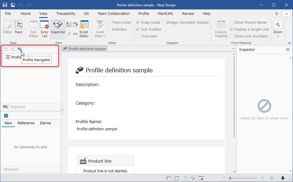
- Select [Profile Navigator] from the selector at the top of the navigator to switch the navigator.
- Click [View] > [Pane] > [Inspector] on the ribbon to display the inspector on the right side of the screen.
1.2 Configure the profile
Add an entity directly under the project
To broadly classify the model types directly under the project, add the [Requirement model] entity as follows.

- Right-click [Project definition sample] displayed at the top of the profile navigator, and click [Add] > [Metamodel] > [Entity] from the context menu.
- In the [New Entity] dialog, enter the items as shown in the table below and press the [OK] button.
| Item | Value |
|---|---|
| [Display Name] | Enter "Requirement model" as the name |
| [Class Name] | (The same name as the display name will be automatically entered) |
| [Icon] | Select an icon from the options |
Change definition so that it can be placed directly under the project
When modeling, only certain entities can be added directly under the project in the model navigator. To allow the [Requirement Model] added in the previous step to be added directly under the project, change the definition as follows:
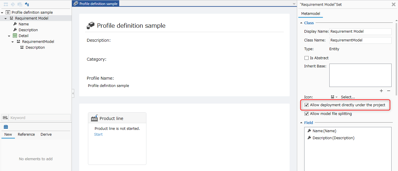
- Select [Requirement Model] in the Profile Navigator to display the details in the Inspector.
- Check [Allow deployment directly under the project] in the Inspector.
Create a package and add a [UseCase Model] entity
To create a package in the profile and add a [UseCase Model] entity, follow the steps below.

- Right-click [Project definition sample] displayed at the top of the Profile Navigator, and click [Add] > [Package] from the context menu.
- Right-click the added package, click [Rename] from the context menu, and change the name to [UseCase Model].
- Next, click [Add] > [Metamodel] > [Entity] from the package's context menu.
- In the [New Entity] dialog, enter [UseCase Model] in [Display Name], select [Icon], and click the [OK] button.
1.3 Prepare a class diagram to define the metamodel
Add a class diagram to [UseCase Model]
To define the metamodel of [UseCase Model] in the UML class diagram format, add a class diagram using the following procedure.

- Right-click the [UseCase Model] package on the Profile Navigator, and click [Add Class Diagram] from the context menu.
- Enter [UseCase Model Structure Diagram] as the name of the class diagram added to the Profile Navigator.
Configure parent-child relationships for [UseCase Model]
To create a hierarchical model during modeling, you need to connect the parent-child entities with an ownership relationship.
To be able to add [UseCase Model] under [Requirement Model] during modeling, connect the ownership relationship with the following steps.
- Double-click [UseCase Model Structure Diagram] to open the class diagram.
- Drag and drop [Requirement Model] and [UseCase Model] from the Profile Navigator to add them to the class diagram.
- To create an association, move the pointer to the parent [Requirement Model], drag the [▲] icon displayed on its four sides, and drop it on the [Use Case Model] to which you want to associate it.
- When you drop it, a pop-up will appear with options for the type of association, so click [Embedded] to select it.
- This creates an ownership association from [Requirement Model] to [Use Case Model], and defines the parent-child relationship between [Requirement Model] and [Use Case Model].
2. Define the structure of the use case model
To define the structure of the [Use Case Model], add the entities [Actor] and [Use case] to the class diagram and associate them. The steps are as follows:
- Add [Actor] and [Use case] as entities.
- Add fields to the entities.
- Associate the entities to define the structure of the [Use Case Model].
2.1 Adding an entity
To add an entity to a class diagram, follow these steps.
- Drag and drop [Entity] from the class toolbox to add it, and enter a name.
- Here, add [Actor] and [Use case] as entities.
- If you select an entity and press the delete key, it will simply be hidden on the class diagram, just like [Delete From Diagram] in the context menu, but it will not be deleted from the metamodel and will remain in the profile navigator.
- To delete an entity that you added by mistake, execute [Delete From Model] from the context menu of the entity.
To change the icon of an added entity, follow these steps.
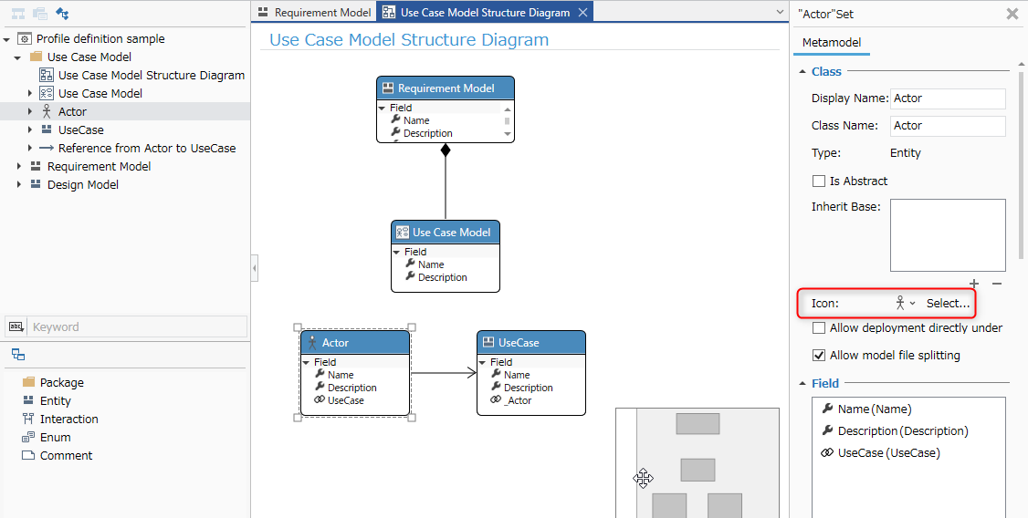
- Select the entity whose icon you want to change in the class diagram.
- Select the icon in the Inspector.
2.2 Add a Field to an Entity
To add a field to hold data to an entity, follow these steps:
- Move the pointer over the entity in the class diagram.
- Click the [+] icon that appears on the right side of [Fields]. Here, add a [Precondition] field (string type) to the [Use case] entity as follows.
- In the [Add New Fields] dialog, enter the items as shown in the table below and press the [OK] button.
| Item | Value |
|---|---|
| [Display Name] | Enter "Precondition" as the name |
| [Field Name] | (The name will be automatically filled in with the same name as the display name) |
| [Data Type] | Select [String] from the options |
2.3 Associate entities to define structure
To add another entity as a child element that composes an entity, create an ownership relationship that represents a parent-child relationship between entities.
Also, to associate entities that have a relationship other than a parent-child relationship, such as [Actor] and [Use case], create a reference relationship between entities.
Here, we define the following two types of relationships as the structure definition of [UseCaseModel].
| Relationship | Description |
|---|---|
| Ownership relationship from [UseCaseModel] to [Actor] and [Use case] | You can add [Actor] and [Use case] as children of [UseCaseModel]. |
| Reference relationship from [Actor] to [Use case] | You can now associate [Actor] with [Use case]. |
- Move the pointer over the entity of the source of the relationship.
- Drag the [▲] icon displayed in four directions and drop it on the entity of the destination of the relationship.
- A pop-up will appear with options for the type of relationship, so click to select it.
- As with deleting an entity, if you select an association line on a class diagram and press the delete key, it will simply be hidden on the class diagram, but will not be deleted from the metamodel and will remain on the profile navigator.
- To delete an association that you added by mistake, execute [Delete From Model] from the context menu of the association line.