Modeling guide
Overview
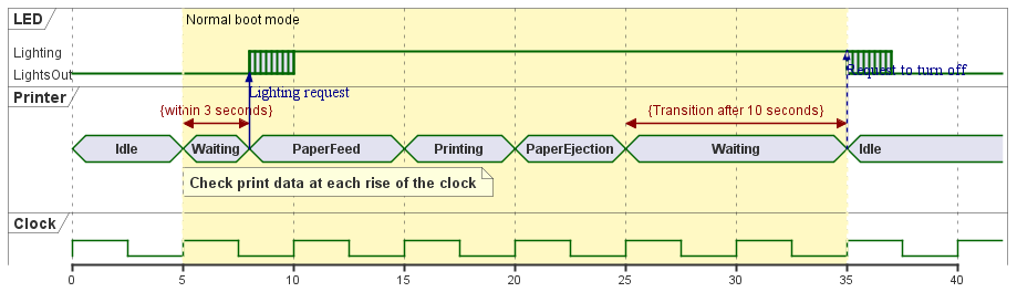
Timing charts can be used to represent state changes within and between lifelines along the time axis.
This page describes the operations for using the timing chart in the following order.
- Arrange the timing chart
- define lifelines
- Define state transitions
- define a message
- define time constraints
- define notes
We also provide the following features to assist users in modeling:
- decorate the timing diagram
- validate the model
Placing a timing chart
Follow the steps below to place a timing chart.
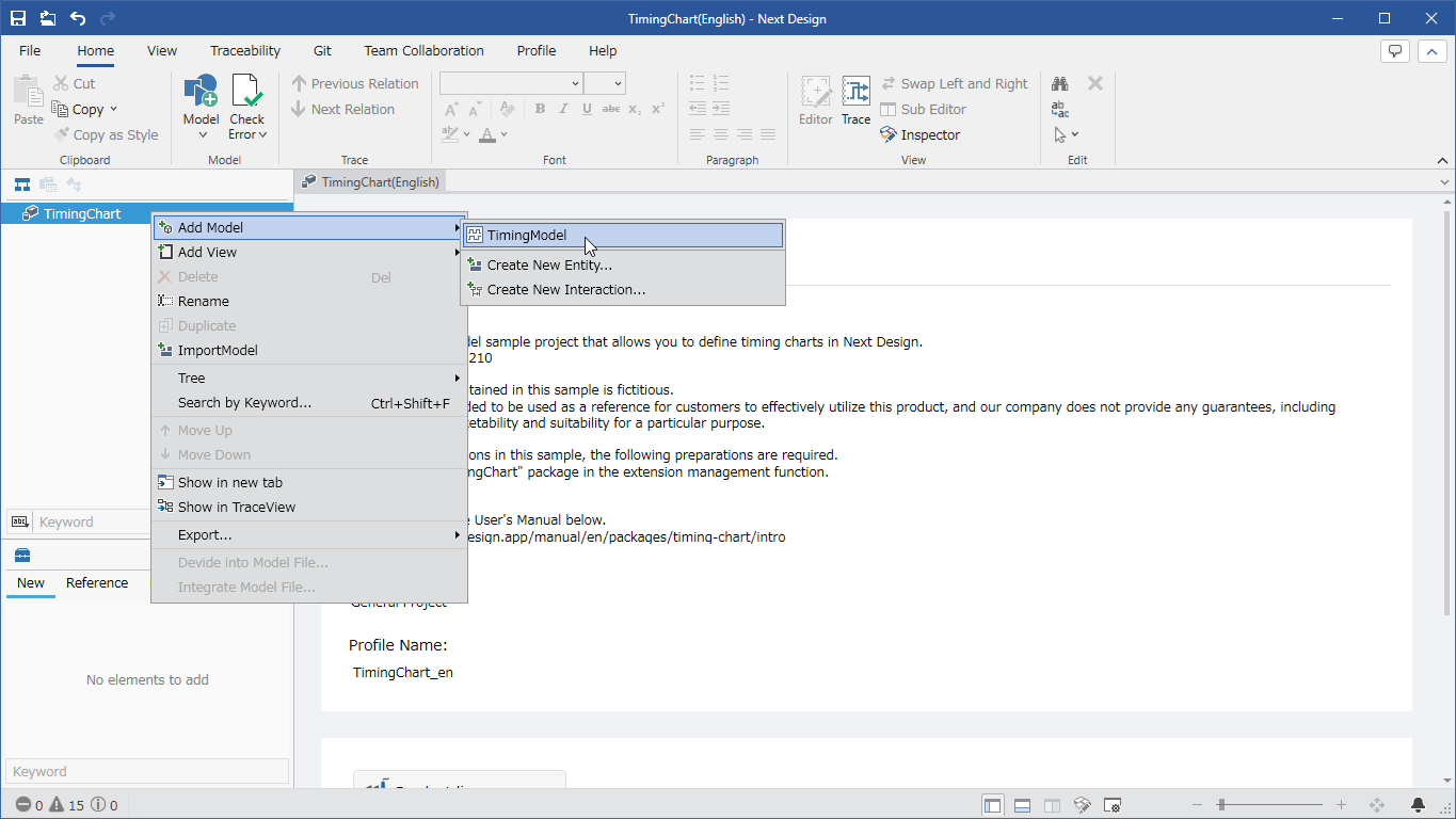
- Select a package in the model navigator and click [Add Model] > [Timing Model] in the context menu.
- Timing Model is placed as a child element of the selected package.
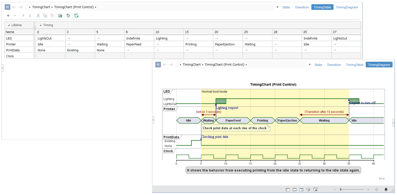
The timing model has multiple views defined for defining timing charts.
The defined views are:
| View Name | Features |
|---|---|
| State | You can define the type and state of a lifeline. |
| You can define transitions and their destinations, time constraints, messages, and notes in | Transitions |
| Timing Table | The defined lifelines and timings are displayed in table format. Design focused on transitions can be done more efficiently. |
| Timing Chart | Displays a timing chart based on the data defined in the timing model. |
define a lifeline
To define the following lifelines in the timing diagram, follow the steps below.

Add Lifeline
To add a lifeline to your timing diagram, follow these steps:
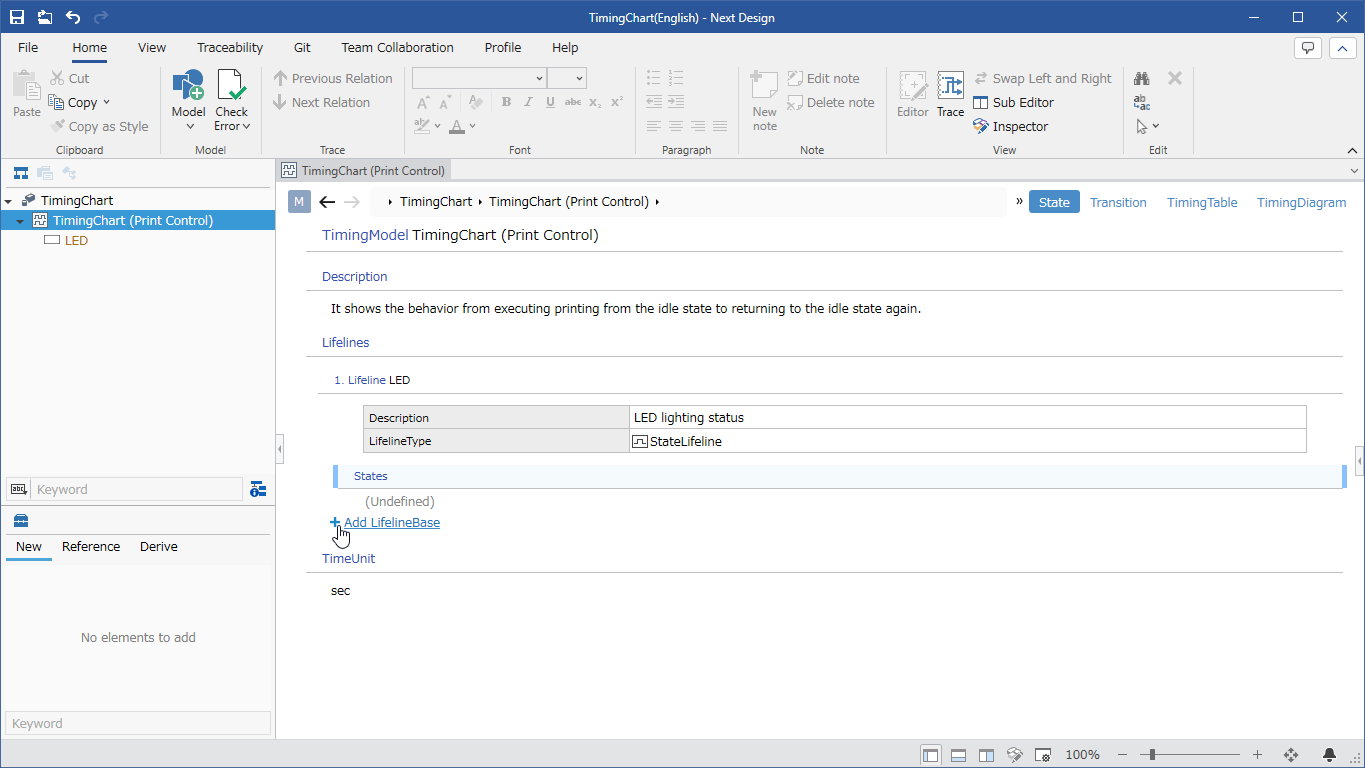
- Select Timing Model and switch to the State view.
- Click the + icon link that appears when you move the pointer over the Lifeline field.
- Select Lifeline in the dropdown list to add a lifeline.
A clock lifeline can be used to represent a state that changes at regular intervals, such as a clock.
To add clock lifelines for timing diagrams:
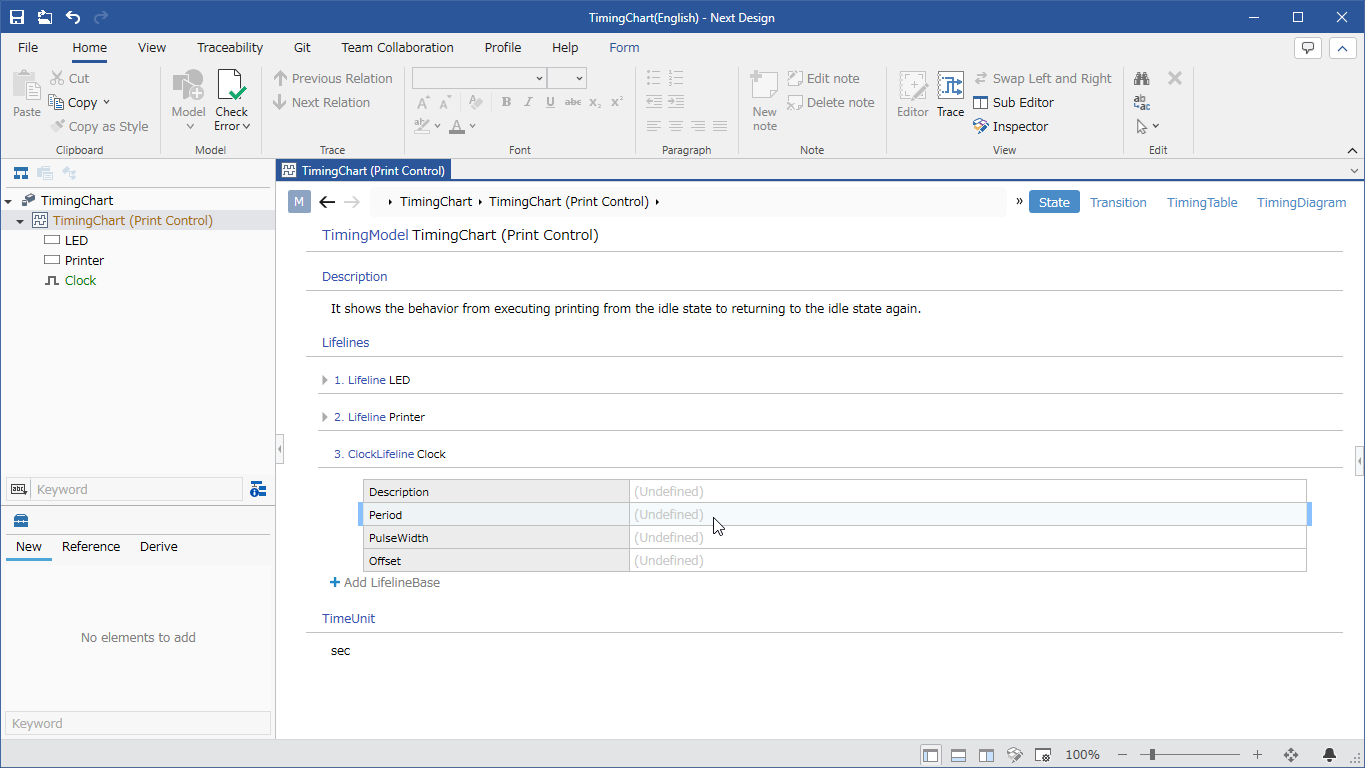
Operating procedure
- Select Timing Model and switch to the State view.
- Click the + icon link that appears when you move the pointer over the Lifeline field.
- Select Clock Lifeline from the dropdown list to add a clock lifeline.
- Enter the information of the period you want to create in the [Period], [Pulse Width], and [Offset] fields of [Clock Lifeline] to add a periodic lifeline.
Add State
To add a state to the lifeline of the timing diagram, follow these steps:
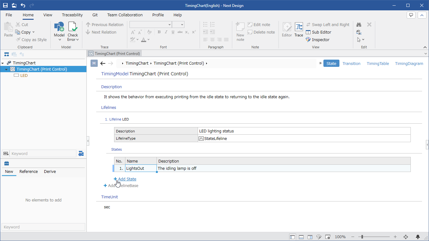
- Select Timing Model and switch to the State view.
- Click the + icon link that appears when you move the pointer over the Lifeline State field.
- Select State from the dropdown list to add a state.
- If you select [Indefinite State] from the list in step 3, you can add an indefinite state.
Define state transitions
To display the following state transitions in the timing diagram, define them as follows:

Add Timing
To add a transition timing, follow the steps below.
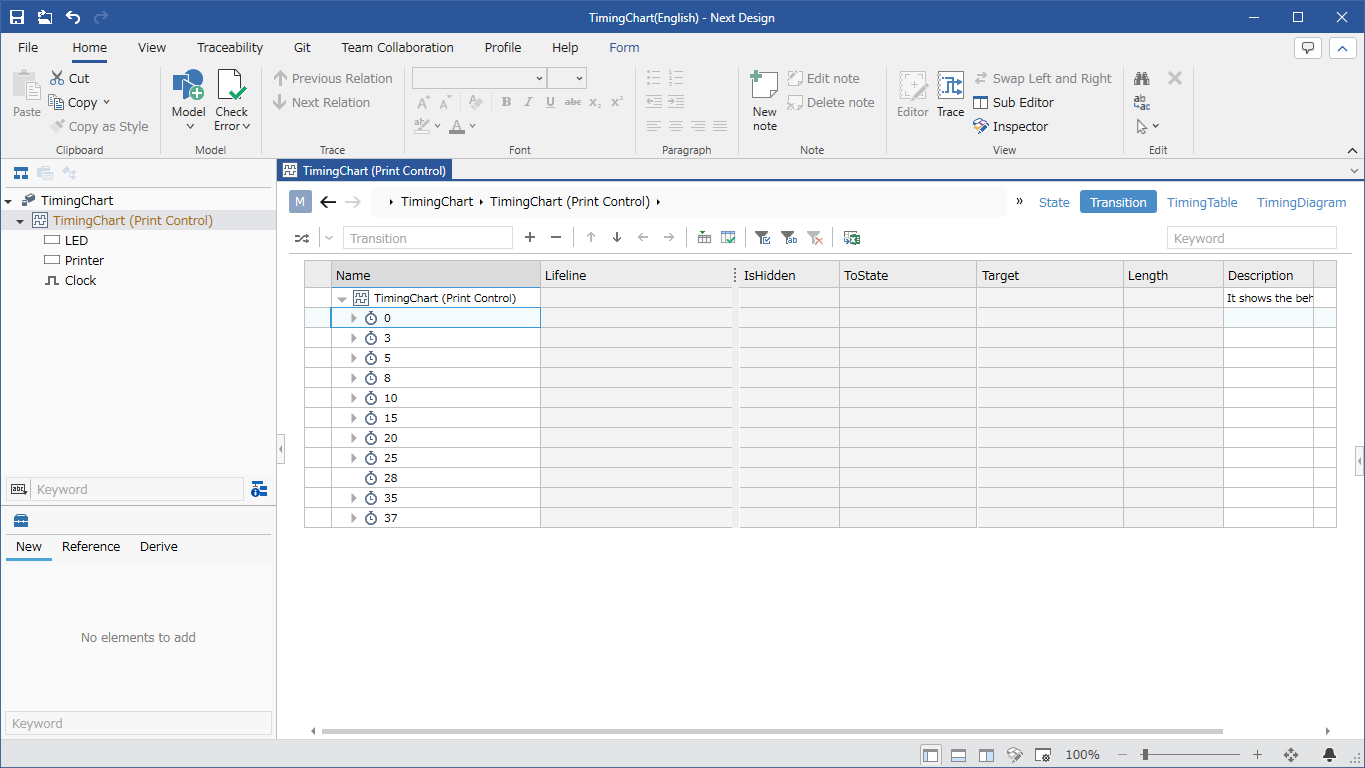
- Select Timing Model and switch to the Transitions view.
- Select a cell in the Timing Model row, enter the name of the timing to be added in the text box on the toolbar above the tree grid, and press Enter.
- A new [Timing] is added at the end of the [Timing Model] child.
Add a transition
To add transitions:
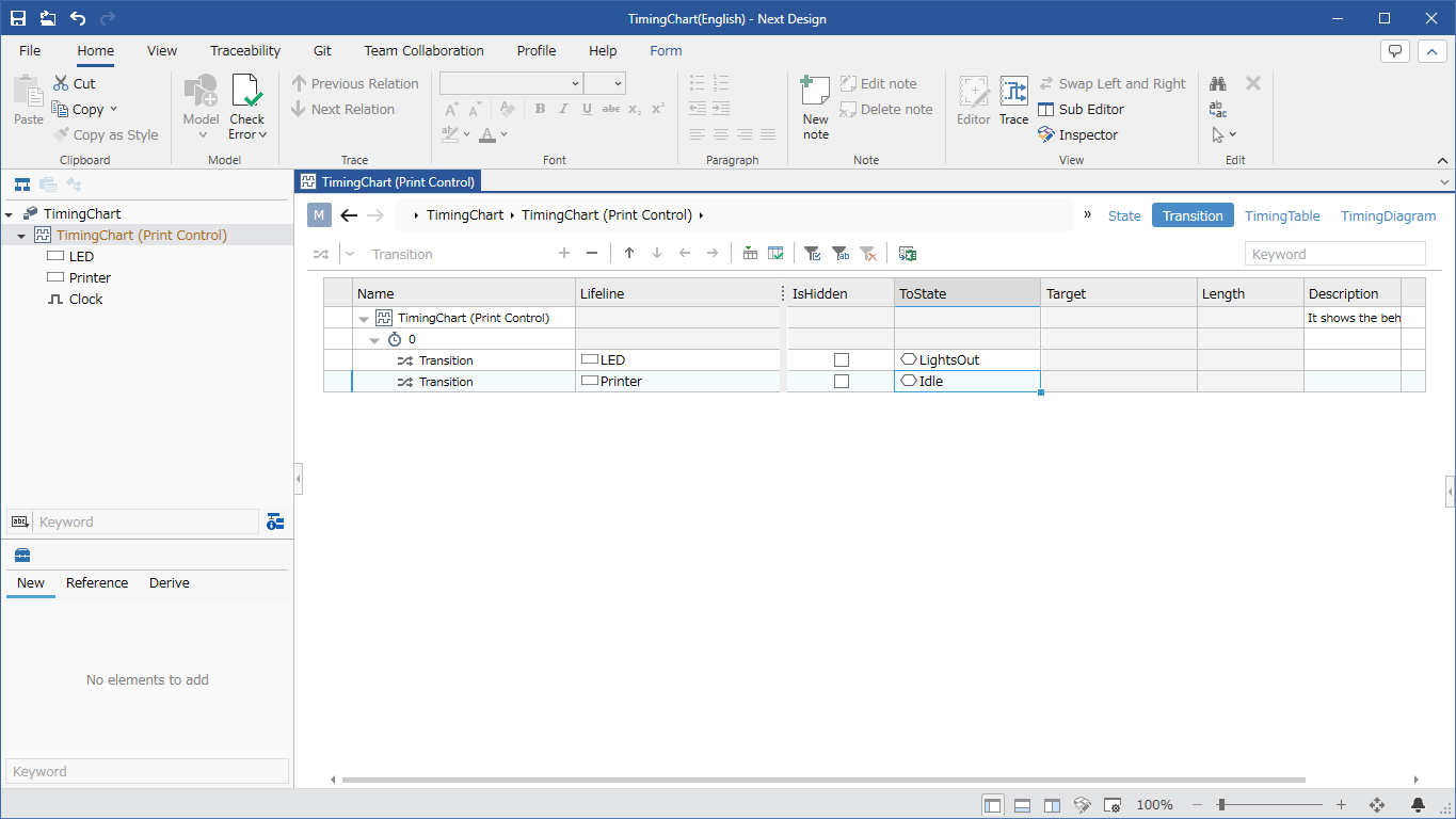
- Select Timing Model and switch to the Transitions view.
- Select the cell in the [Timing] row where you want to add a transition, open the leftmost pull-down list from the toolbar at the top of the tree grid, and select [Transition].
- Enter the name of the transition to add in the text box to the right of it and press Enter.
- A new [Transition] is added at the end of the [Timing] child, so enter the information of the transition you want to create in the [Lifeline] and [Transition destination] fields of [Transition].
Transition design can be performed efficiently by using the [Timing Table] view.
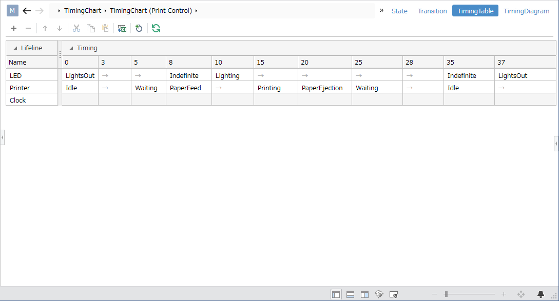
- The [Timing Table] view is displayed in a grid format with lifelines as rows and timings as columns. Cells display the state of the transition destination to which the lifeline of that row transitioned at that timing.
- This enables efficient transition design while considering transitions between lifelines.
You can hide the state of a particular lifeline for a particular period of time to express that it is out of design range.
To hide the state for a specific period, define it as follows:
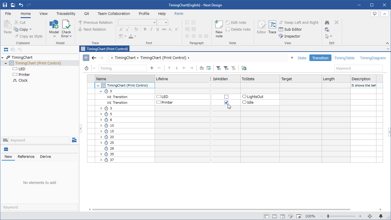
Operating procedure
- Select Timing Model and switch to the Transitions view.
- Enable the check box in the Hidden? field for the Transition you want to hide.
- Switching to the Timing Diagram view hides the state of the lifeline until the next state transition.
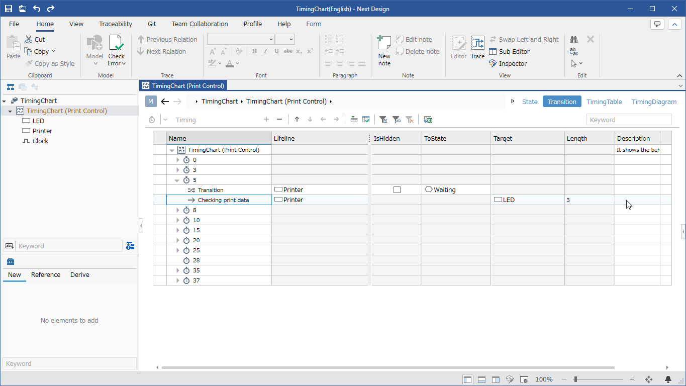
define the message
To display a message like the following in the timing diagram, define it as follows:
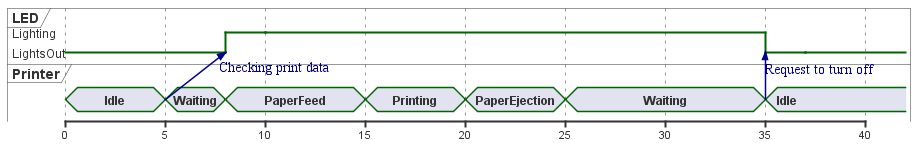
Add message
To add messages between lifelines, follow these steps:
- Select Timing Model and switch to the Transitions view.
- Select [Timing], which is the start time of the message, open the leftmost pull-down list from the toolbar at the top of the tree grid, and select [Message].
- Enter the name of the message to be added in the text box to the right of it and press Enter.
- [Message] is added to the selected [Timing], so enter the start point of the message in the [Lifeline] field, the end point of the message in the [Destination] field, and the difference between the end time and start time of the message in the [Duration] field. To do.
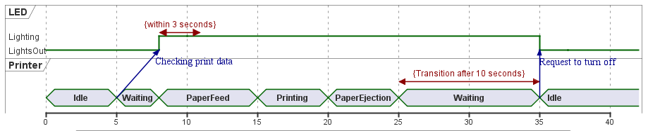
Define time constraints
To display the following time constraint in the timing diagram, define it as follows:
Add Time Constraint
To add a time constraint, do the following:
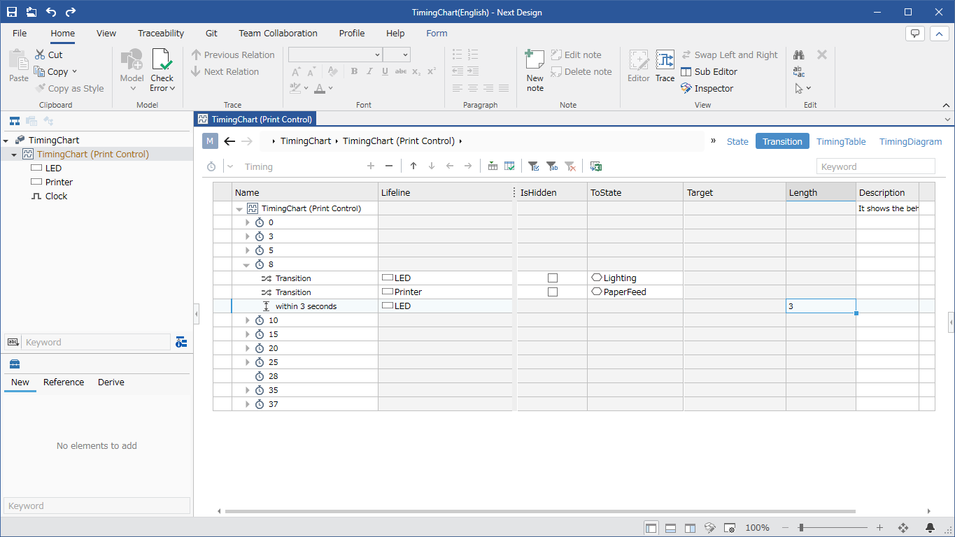
- Select Timing Model and switch to the Transitions view.
- Select [Timing], which is the start time of the time constraint, open the leftmost pull-down list from the toolbar at the top of the tree grid, and select [Time constraint].
- Enter the name of the message to be added in the text box to the right of it and press Enter.
- [Time Constraint] will be added to the selected [Timing]. Enter the setting destination of the time constraint in the [Lifeline] field and the time to apply the constraint in the [Duration] field.
define a note
To display the following notes in the timing diagram, define them as follows:

Add Note
To add notes, follow these steps:
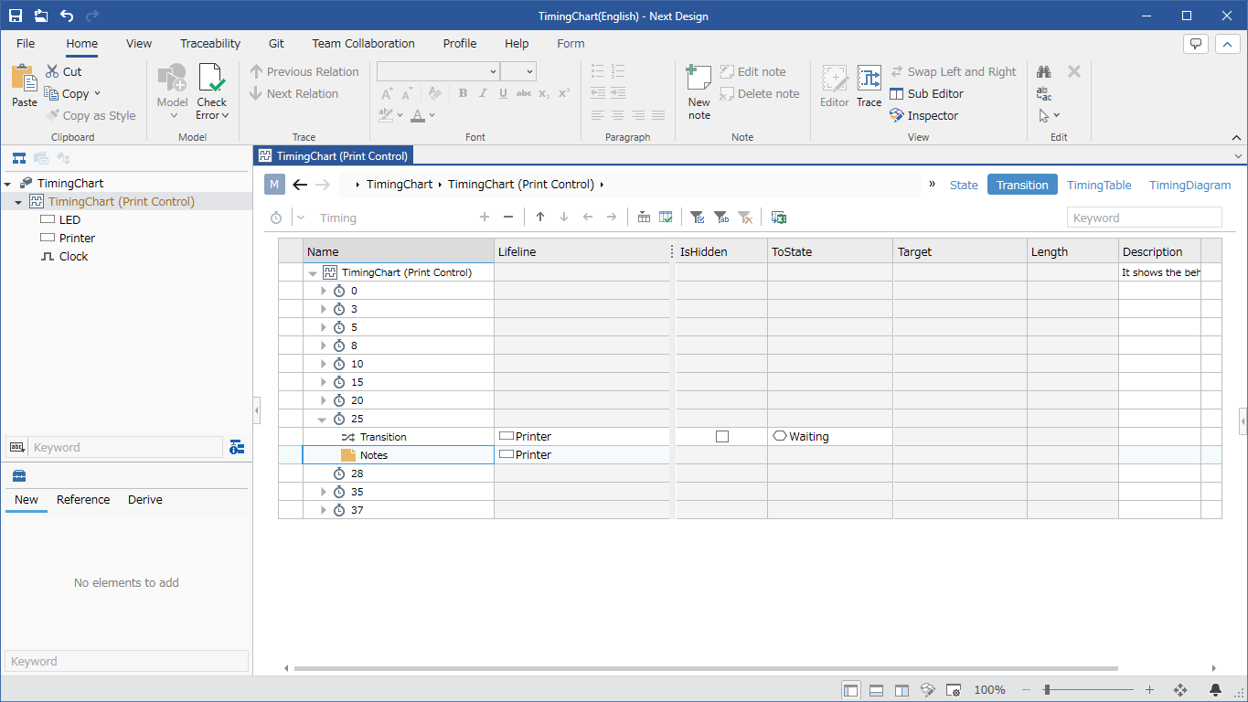
- Select Timing Model and switch to the Transitions view.
- Select the [Timing] where you want to add a note, open the leftmost pull-down list from the toolbar at the top of the tree grid, and select [Note].
- Enter the name of the message to be added in the text box to the right of it and press Enter.
- [Note] will be added to the selected [Timing], enter the content to be displayed in the [Name] field.
- Notes appear in timing diagrams only when added with a generic value lifeline.
Decorate the timing diagram
You can decorate your timing diagrams from the Timing Diagrams tab of the Inspector.
Follow the steps below to set the highlights.
- With the Inspector displayed, select Timing and switch to the Timing Diagrams tab.
- Enable the check box for Emphasize Timing in the Style group.
- You can enter [End Timing], [Caption], [Fill Color], and [Border Color], so set any value for each.
- When the [Timing Diagram] view of the [Timing Model] is displayed, the highlights are set according to the settings.
From the Inspector's Timing Diagram tab, the available decorations are:
| Decoration contents | Target model (display name) |
|---|---|
| Timing Diagram Title | Timing Model |
| Description of Timing Diagram | Timing Model |
| Timing Diagram Magnification | Timing Model |
| Timing Diagram Scale | Timing Model |
| Highlights | Timing |
| Background color of post-transition state | Transition (*1) |
| Border color of post-transition state | Transition (*1) |
| note position | note |
- 1: Can be set when the transition refers to the general value lifeline.
Validate the model
The items verified by the timing model are as follows.
- Does the transition have a destination state, except for hidden ones?
- Are the timing values standardized in the format specified by the timing model?
- Is the note set to Generic Value Lifeline?
- Are two or more undefined candidate states specified?
- Is an indeterminate state specified as an indeterminate state candidate state?
To validate your model, follow these steps:
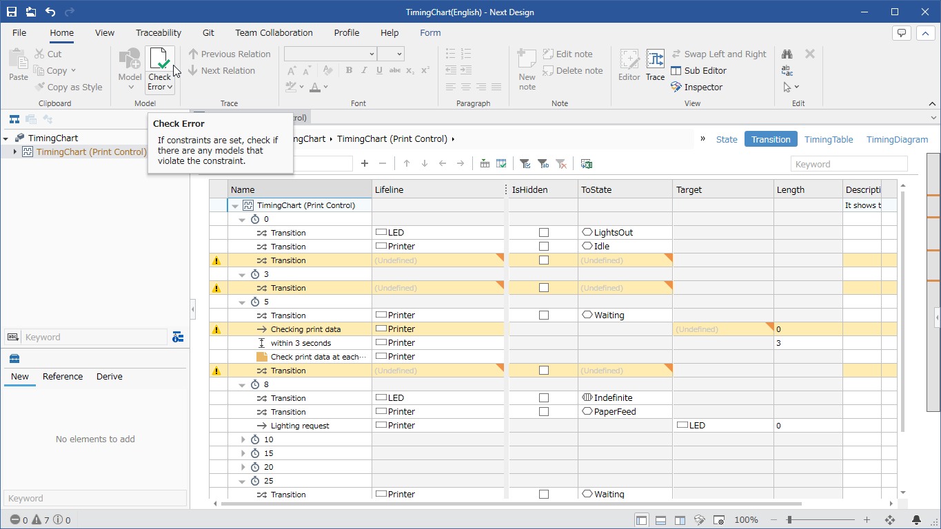
- Run Home > Model > Check Error from the ribbon.
- If all models under the project are inconsistent, an error will be displayed.
- Validation results are automatically updated, but may not be automatically updated during some editing operations. Before using the timing diagram, be sure to verify it according to the operating procedure.