Displaying Any Model on a Diagram
ER diagrams are designed by arranging the child elements and referenced models that make up the model being edited. In addition, models that are not directly related to the model being edited (other than child elements and referenced models) can also be placed on the same ER diagram.
For example, use cases from the requirements analysis phase and components from the design phase are designed in different phases, so they are not listed side by side as the same design outcome. However, if you want to see the connection between design outcomes between phases, you can express the relationship by placing them on the same ER diagram.
In Next Design, when adding a shape definition to an ER diagram, you typically specify a field as the shape's mapping target. However, you can also specify any class instead of a field. This allows you to place use cases and components designed in different phases on a single ER diagram. Such shapes are called class-specified shapes.
The following explains an example of placing components, which are the design results of different processes, on a use case diagram whose view was defined in the Quick Start.
- Adding component shape definitions to a use case diagram
- Placing existing components on a use case diagram
- Adding connector definitions to represent the relationship between use cases and components
Adding component shape definitions to a use case diagram
Shape definitions must be added to be able to place models on an ER diagram. To add a shape definition for a component that is not directly related to the use case diagram, follow these steps:
- Prepare a project with all use case and component profiles defined according to the User's Manual > Quick Start.
- Select the [Use Case Model] in the Model Navigator to display the [Use Case Diagram] view.
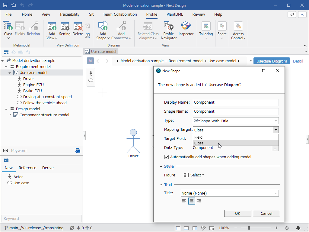
- Click [Profile] > [Diagram] > [Add Shape] on the ribbon and click the type of shape you want to add.
- In the [New Shape] dialog box, set the following:
- Select [Class] for [Mapping Target].
- Click the [...] button to the right of [Data Type] and select [Component] from the list of entities.
- Select the shape type in [Diagram] under [Style].
- Click the OK button in the dialog box to add a Component icon to the Toolbox.
Placing an Existing Component on a Use Case Diagram
After adding a component shape definition to a use case diagram, follow these steps to place the existing component on the use case diagram.
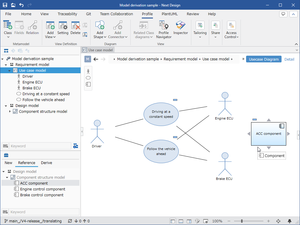
- Select a Use Case Model in the Model Navigator to display the Use Case Diagram view.
- Switch the Toolbox below the Model Navigator to the Reference tab to display a list of existing components that can be placed on the use case diagram.
- Drag and drop the existing component displayed in the Reference tab of the Toolbox onto the use case diagram.
- If the existing model does not appear in the Reference tab of the Toolbox, refresh the display of the model you want to edit using one of the following methods:
- Switching views in the Model Editor
- Switching selections in the Model Navigator
Adding a connector definition to represent the relationship between a use case and a component
To connect a use case and a component in a use case diagram, add a connector definition using the same procedure as below.
:::see note
:::