ER diagram view definition
Overview
Next Design allows you to define a view for an ER diagram that can represent the structure of a model and the relationships between models in diagram form.
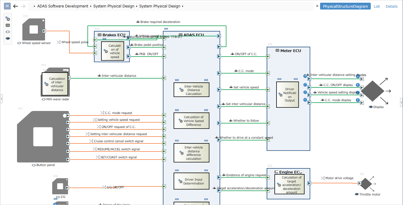
ER diagram view definition allows you to express various diagram designs by specifying the following notation methods.
- Shape: Shape of each entity
- Connector: Relationship line between entities
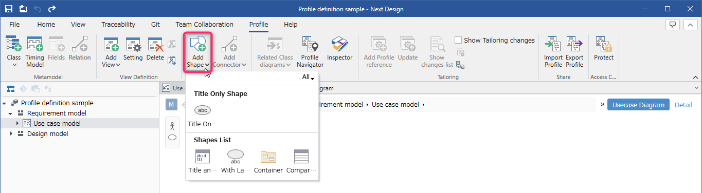
There are the following types of shapes.

| Shape types | Description |
|---|---|
| Title Only Shape | A title is added inside the shape. |
| Title and Description | A title and a body such as a description are added to the shape. |
| With Label | A title is added to the outside of the shape. |
| Container | Related models can be nested as shapes. |
| Compartment | Multiple fields can be displayed within the shape. |
| Port | Can be placed on the edge of the shape as a connector contact. |
| Child Shape | Related models can be nested as shapes. |
There is only one type of connector. You can change the style of the connector to include a broken line or arrow.
The following describes how to define the ER diagram view in the following order.
- Define a shape
- Define a connector
Define a shape
Add a shape
To add a shape to the diagram view definition, follow the steps below from the Model Editor.
- For instructions, see the following:
Quick Start > Profile Definition > Define Diagram View > Add a Shape by Entity
- Of the shape types, [Port] and [Child Shape] cannot be added unless the parent shape is selected. For details, see "Add a Child Shape" below.
Changing the type and shape of a shape
To change the type and shape of a shape that has already been added to a view definition, follow the steps below in the Model Editor.
- Select the shape you want to change on the view.
- To change the type of a shape, click [Add Shape] > [Node] > [Change Shape Type] on the ribbon, and click a type from the options.
- To change the shape of a shape, click [Add Shape] > [Style] > [Change Shape] on the ribbon, and click a shape from the options.
- In addition to the standard built-in shapes, you can also use your own images as shapes.
- For details, see How To > Profile Definition > View Definition > Use Images in Diagrams.
- After changing the shape type, an extra label (such as the model name) may remain displayed. In that case, delete the unnecessary label by following "Changing the label of a shape" described later.
Change the default style of a shape
There are two ways to change the style of a shape:
- Change the style of an individual model displayed in a diagram
- Change the default style of a shape defined for each entity as a view definition of the diagram
This section describes the latter procedure. For the former, see Modeling > Edit Model > Edit ER Diagram.
To change the default style or size of a shape, follow the steps below.
- Select the shape you want to change on the view.
- Change the default style of the shape using the following UI:
- [Add Shape] > [Style] > [Change Shape], [Quick Style], [Fill Color], [Line Color], [Font Color] on the ribbon
- [Shape Definition] tab > [Style] > [Diagram], [Color], [Border Thickness], [Show metamodel icon] on the Inspector
- Change the default size of the shape using one of the following methods.
- Change the size of the selected shape and click the Add Shape > Size > Set Default Size from Selected Shape button on the ribbon.
- Enter the width in the top row of Add Shape > Size > Default Size on the ribbon and the height in the bottom row.
- Enter values in the Shape Definition tab of the Inspector > Default Size > Width and Height.
- If you want to change the distance between the border of a child shape, use the following UI to change the padding.
- Enter values in the Shape Definition tab of the Inspector > Default Size > Padding.
- Changing the default size of a shape does not change the size of the selected or existing shapes.
- Shapes you add after changing the default size will be the default size.
Changing an entity's icon
To change the icon of an entity displayed in the Model Navigator or Toolbox, follow the steps below in the Inspector.
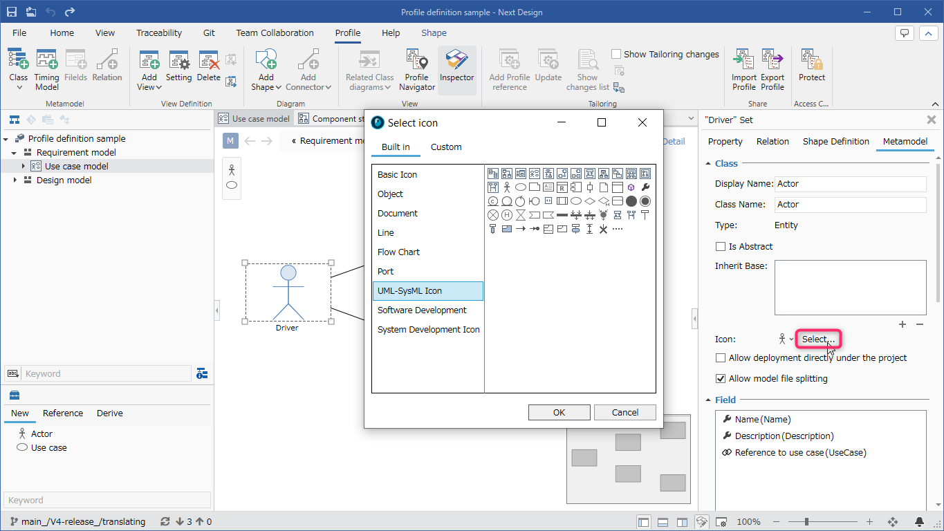
- Click [View] > [Pane] > [Inspector] from the ribbon to display the Inspector on the right side of the screen.
- Select the shape you want to change in the view.
- Select [Metamodel] from the tabs at the top of the Inspector.
- Click [Select] under [Class] > [Icon] and select an icon from the [Select icon] dialog.
Changing the shape label
To change the field displayed in the shape title or body, follow the steps below.
- Select the shape you want to change in the view.
- To change the field displayed in the shape title or body, select the field you want to display from the [Add Shape] > [Text] > [Title] or [Body] pull-down list on the ribbon.
- To change the text alignment of the shape title or body, click [Align Left], [Center], or [Align Right] under [Add Shape] > [Text] > [Title] or [Body] on the ribbon to switch between them.
To change the font settings of the shape title or body, follow the steps below.
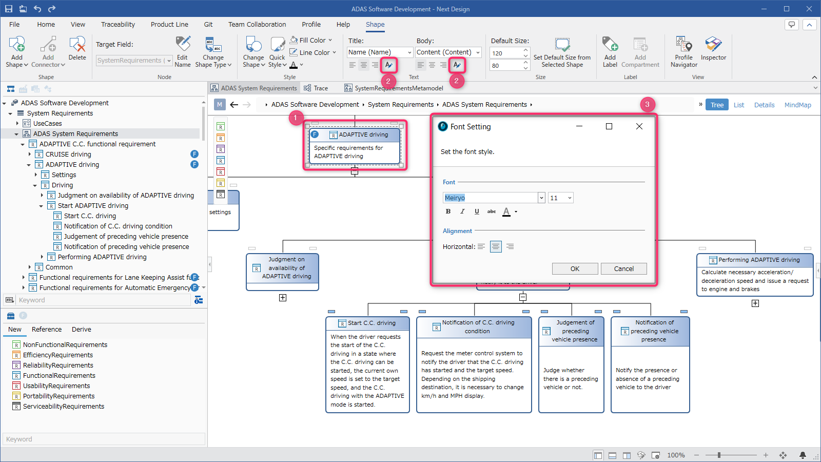
- Select the shape you want to change in the view.
- To change the font settings of the shape title or body, click the [Add Shape] > [Text] > [Title] or [Body] [Font Setting] button on the ribbon to display the [Font Setting] dialog.
- In the [Font Setting] dialog, set [Font Family], [Font Size], [Bold], [Italic], [Underline], [Strikethrough], and [Font Color] and press the [OK] button.
To add or remove a shape label, follow the steps in the Inspector.
- Click [View] > [Pane] > [Inspector] on the ribbon to display the Inspector on the right side of the screen.
- Select the shape you want to change on the view.
- Select [Shape Definition] from the tabs at the top of the Inspector.
- To add a label, click the [+] button below the [Label] list.
- In the [New Label] dialog, select [Fields] and [Layout], enter the text to be used when no value is set in [Hint Text], and click the [OK] button.
- To delete a label, select the corresponding line from the [Label] list and click the [-] button below the list.
Deleting a shape
To delete a shape from the diagram view definition and return the shape corresponding to the entity to an undefined state, follow these steps:
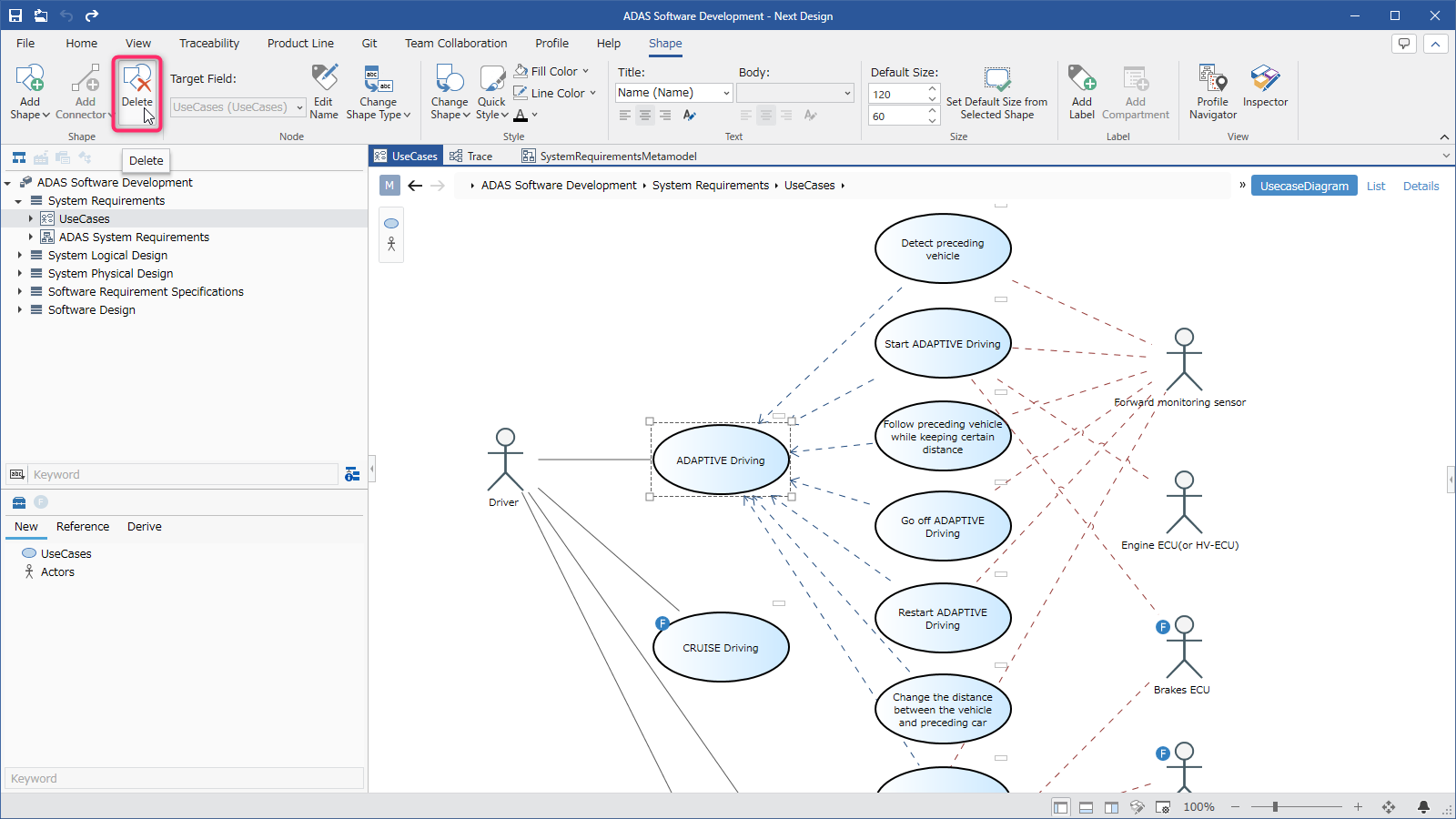
- Select the shape you want to delete on the view.
- Click [Add Shape] > [Add Shape] > [Delete] on the ribbon.
- All the corresponding shapes are deleted from the view, but the models remain. If you add the shapes again, those models will reappear on the view.
- If you delete a shape from the view definition of the ER diagram, the connectors connected to that shape will also be deleted from the view definition.
Add a child shape
To be able to edit related elements of the model as nested shapes in the ER diagram, follow the steps below from the model editor.
- Select the shape that will have a nested shape on the view.
- Add a child shape in one of the following ways:
- Click [Add Shape] > [Add Shape] > [Add Shape] from the ribbon, and click [Child Shape] from the shape list.
- Click [Profile] > [Diagram] > [Add Shape] from the ribbon, and click [Child Shape] from the shape list.
- In the [New Shape] dialog, select the field that holds the related model from the [Target Field] pull-down list, and press the [OK] button.
- You can now drag and drop entities that can be added as related elements from the [Tool Box] into the shape.
- If there are multiple types of entities that can be added as related elements, you need to add a child shape for each of those entities.
Adding a port
To be able to place related elements of a model as ports on the edge of a shape in an ER diagram, follow the steps below in the Model Editor.
- Select a shape on the view that will have a port.
- Add a port in one of the following ways:
- Click [Add Shape] > [Add Shape] > [Add Shape] on the ribbon, and click [Port] from the shape list.
- Click [Profile] > [Diagram] > [Add Shape] on the ribbon, and click [Port] from the shape list.
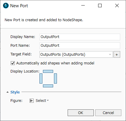
- In the [New Port] dialog, select the field that holds the related model from the [Target Field] pull-down list.
- Next, select a location where the port can be placed in [Display Location].
- Next, select the port shape in [Diagram] and press the [OK] button.
- You can now drag and drop entities that can be added as related elements from [Tool Box] to the edge of the shape.
- If you want to set up input and output ports, define two relationships in the metamodel and then add ports for each relationship.
Changing compartment partitions
If the shape type is [Compartment], you can display any field in the area below the title. To add a field to be displayed in a compartment, follow the steps below.
- Select the shape you want to change on the view.
- Click [Add Shape] > [Label] > [Add Compartment] from the ribbon.
- In the [New Compartment] dialog, select the field you want to add from [Fields] and press the [OK] button.
To change the order of fields displayed in a compartment or remove them from a compartment to hide them, follow the steps in the Inspector.
- Click [View] > [Pane] > [Inspector] from the ribbon to display the Inspector on the right side of the screen.
- Select the shape with compartments you want to change on the view.
- Select [Shape Definition] from the tab at the top of the Inspector.
- Select the field listed in [Compartments], and use the [↑] and [↓] buttons below the list to change the order, or the [-] button to remove it from the compartment.
Define a connector
Add a connector
If the reference relationship between entities is already defined in the metamodel, add a connector definition as in the following procedure.
If the reference relationship between entities is not yet defined, follow the procedure below to add the reference relationship between entities and the connector definition at the same time.
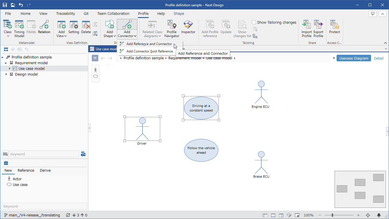
- Select the two models you want to connect with an association line on the ER diagram by holding down the ctrl key and clicking them.
- From the ribbon, click [Profile] > [Diagram] > [Add Connector], click [▼] at the bottom, and click [Add Reference and Connector].
- Check the direction of the association in [Connection Source] and [Connection Target] in the [New ConnectorShape] dialog.
- Next, select [Icon] and set the [Style] item.
- When you press the [OK] button in the dialog, the reference association between the entities and the connector definition are added to the metamodel, and the association line is added to the ER diagram.
Changing the default style of connectors
As with changing the style of shapes, there are two ways to change the style of connectors:
- Change the style of individual association lines displayed in the ER diagram
- Change the default style of connectors defined for each association as a view definition of the ER diagram
This section explains the latter procedure. For the former, see Modeling > Edit Model > Edit ER Diagram.
To change the default style of connectors, follow the steps below.

- Select the connector you want to change on the view.
- Use the following UI to change the default style of connectors.
- Ribbon [Add Connector] > [Style] > [Connection Source], [Connection Target], [Connection Form], [Quick Style], [Fill Color], [Line Color]
- Inspector [Shape Definition] tab > [Style] > [Connection Source], [Connection Target], [Connection Form], [Color], [Border Thickness], [Line Style], [Show metamodel icon]
Change connector label
To add a label to a connector, follow these steps:
- Select the connector you want to change on the view.
- Click [Add Connector] > [Add Label] from the ribbon.
- In the [New Label] dialog, select [Fields] and [Layout], enter text for when no value is set in [Hint Text], and click the [OK] button.
- Edit the connector field values in the [Property] tab of the Inspector.
To change or delete a connector label, follow the steps in the Inspector.
- Click [View] > [Pane] > [Inspector] from the ribbon to display the Inspector on the right side of the screen.
- Select the connector you want to change on the view.
- Select [Shape Definition] from the tab at the top of the Inspector.
- To change the label of a connector, point to the corresponding line listed in [Label] and click the [Edit Label] button that appears at the right end of the line.
- In the [Setting - Label] dialog, change [Files] and [Layout] and click the [OK] button.
- To delete a connector label, select the corresponding line listed in [Label] and click the [-] button below the list.
Changing connector settings
To change settings such as the directionality of the connector connection, follow the steps below in the Inspector.
- Click [View] > [Pane] > [Inspector] from the ribbon to display the Inspector on the right side of the screen.
- Select the connector you want to change on the view.
- Select [Shape Definition] from the tabs at the top of the Inspector.
- Change the settings in the [Add Shape] group.
- For details on the connector settings, see Reference > Profile Settings and Modeling Changes.
Delete a connector
To delete a connector from the diagram view definition and return the connector corresponding to the association to an undefined state, follow these steps:
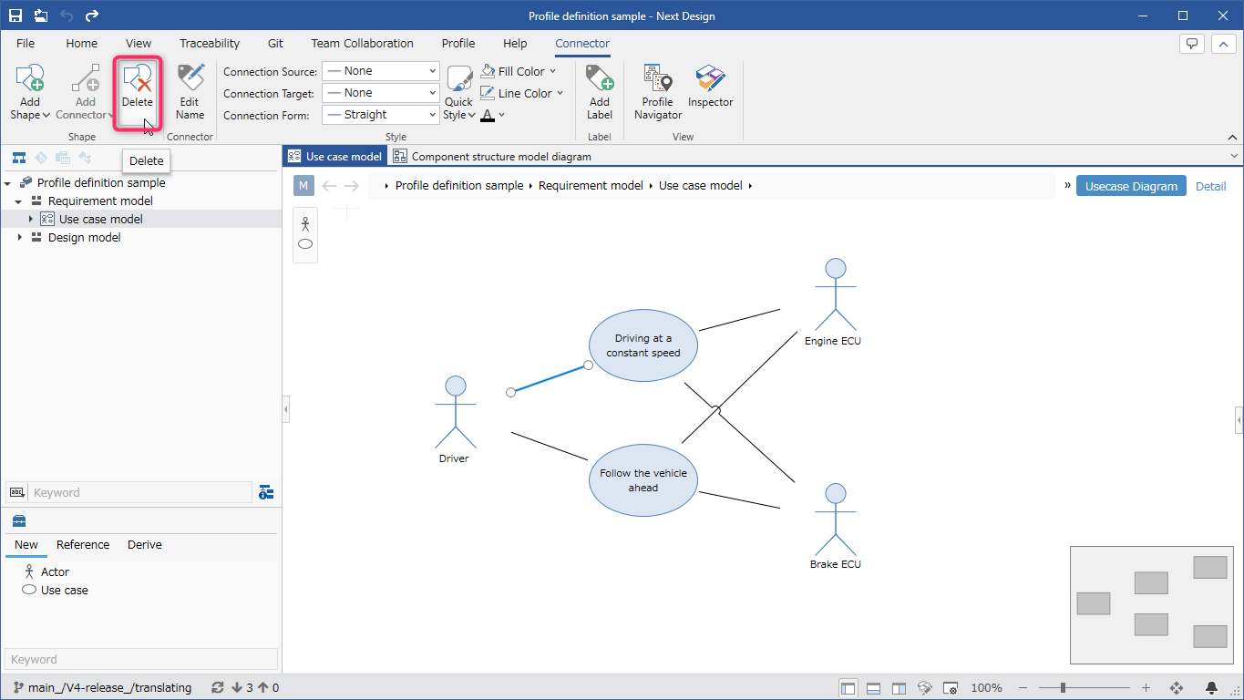
- Select the connector you want to delete on the view.
- Click [Add Connector] > [Add Shape] > [Delete] on the ribbon.
- All the corresponding connectors are deleted from the view, but the associations remain in the model. If you add the connector again, those associations will reappear on the view.