Editing ER diagrams
Overview
Next Design's ER diagram (Entity-Relationship Diagram) allows you to freely place model components on the view and connect components to illustrate the model structure.
Below, we will explain the editing operations in ER diagrams in the following order.
- Add components
- Connect components
- Change shapes
info
- In Next Design, model components are also treated as models, so ER diagram components are also models.
- In the following explanation, to distinguish between them, the object to be edited in an ER diagram will be referred to as a "model", and the components of an ER diagram will be referred to as "model components", or simply as "components".
Adding a component
To add a component to an ER diagram, follow these steps:

Operation procedure
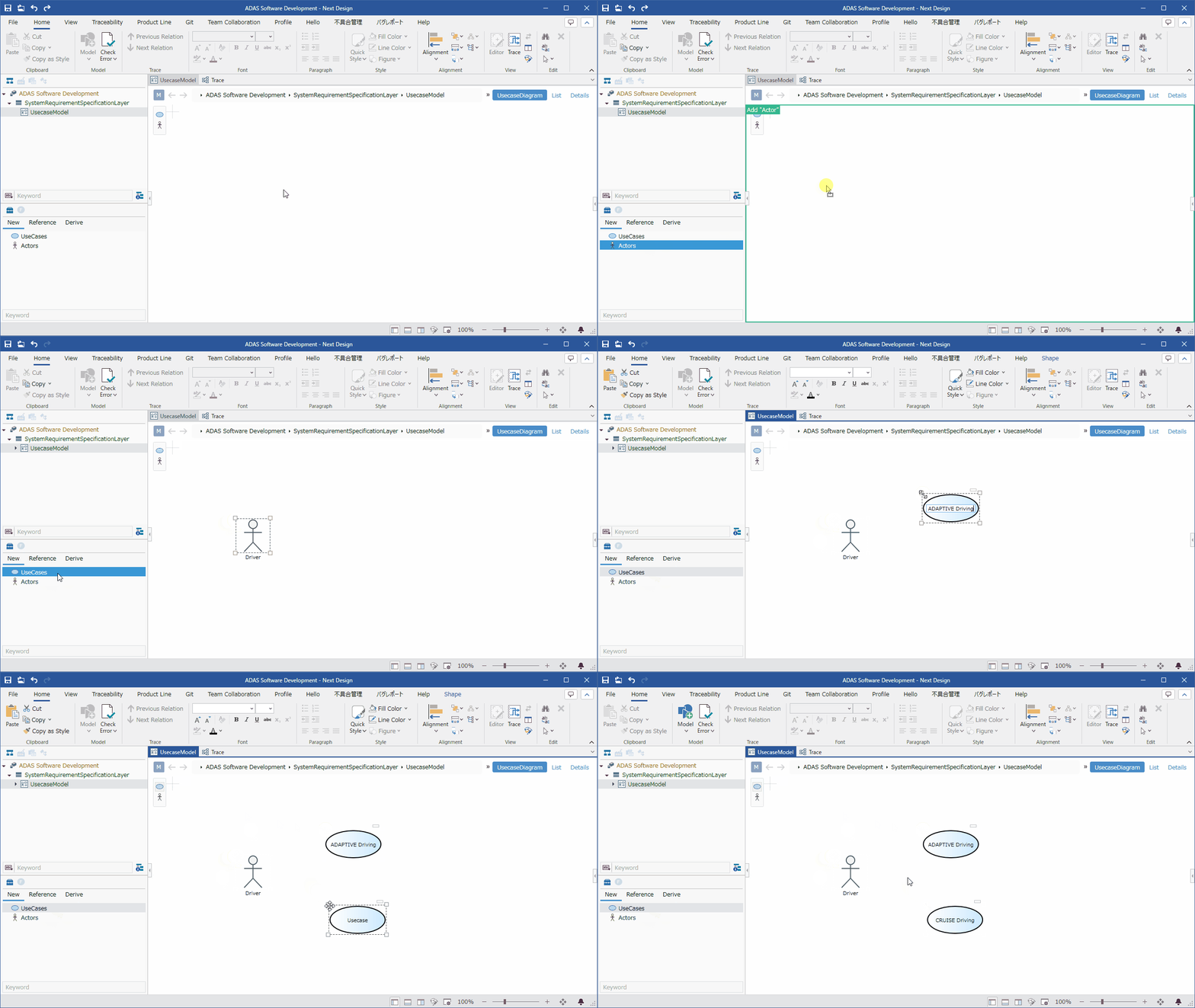
- Follow the basic steps below to drag and drop an entity from the toolbox.
Model Editing > Model Editing Basics > Editing in the Main Editor > Adding a model from the toolbox
- With the added component selected, start typing to edit the component name.
Caution
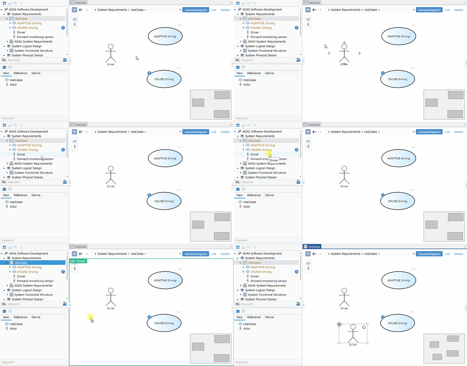
- If you have set the component to be added automatically, if you add a component in another view and then switch to the ER diagram, the added component will be displayed near the existing components, so move it on the ER diagram.
Repeated shapes
- When you add a model that already exists on an ER diagram to the same ER diagram, a circular icon appears in the upper right corner of the component. This icon indicates that there are other components of the same model in the ER diagram. Such components are called Repeated shapes.

Connecting components together
To connect components together in an ER diagram with connectors to show their relationships, follow these steps:

Operation procedure
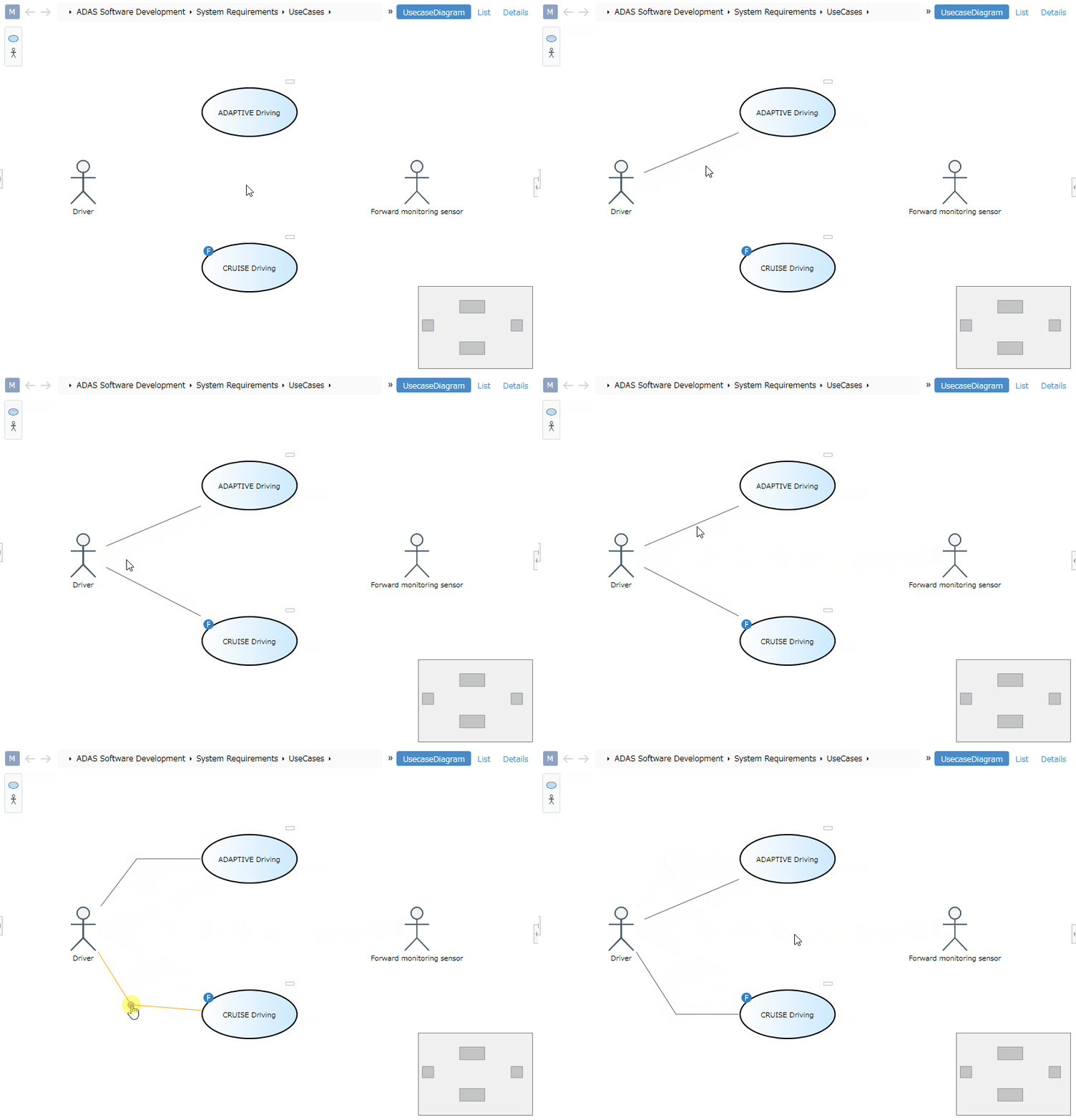
- Move the pointer over the component you want to connect.
- Drag the [▲] icons that appear on all four sides of the component and drop them on the other component you want to connect.
- If there are multiple types of associations, a pop-up will appear with options after dropping, so click to select.
- When components are associated, a connector will appear between them.
- To delete an association, select the connector and press the delete key.
Note
- Associations that do not have a connector defined in the profile cannot be made.
- Whether an association can be made is determined by the combination of the source and destination entities.
To change the shape of each connector, follow the steps below.
Operation procedure
- Select the connector you want to change the shape of and right-click to open the context menu.
- Select one of the following shapes from [Connector Style] in the context menu.
- Straight line
- Orthogonal polyline
- Linear Bezier curve
- Quadratic Bezier curve
tip
- Straight line connectors can be changed to polylines by dragging the middle of the line.
- Orthogonal polyline connectors can be changed by dragging the middle.
- To reset the connector route, execute [Home] > [Alignment] > [Routing] > [Reroute ConnectorShapes] from the ribbon.
- If you move a shape to which an orthogonal polyline connector is connected, the connector route is automatically routed. To stop this automatic routing, click [Home] > [Alignment] > [Routing] > [Auto Routing] from the ribbon to turn it OFF. Note that this setting is saved for each user.
- To switch the display of bridges when connectors cross, switch the [View] > [Diagram] > [Bridge Connector Display] check box on or off from the ribbon. Note that this setting is saved for each user.
- The bridge display is displayed for connectors with shapes other than linear Bezier curves and quadratic Bezier curves.
Changing shapes
To change the shape of a component in an ER diagram, follow the steps below.
Procedure
- Select the component whose shape you want to change.
- Click [Home] > [Style] > [Diagram] on the ribbon.
- Select the shape.
info
- To return a changed shape to its original state, reselect the same shape as in the shape definition.
note
- To be able to change the shape, the [Allow shape change] checkbox in the setting item for the corresponding shape in the profile view definition must be ON.
- For details, see Reference > Profile Settings and Modeling Changes.