Tree diagram view definition
Overview
Next Design allows you to define tree diagram views that allow you to view hierarchical model structures arranged in a tree format.
Based on the Metamodel definition of the model structure, the tree diagram allows you to display and edit only the entities you want to see according to your usage.
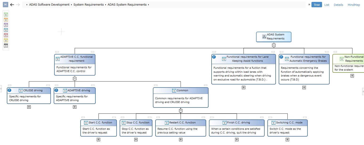
- Entities that can be displayed as child nodes in a tree diagram tree are entities that have owned, referential, or derived relationships with the entity of the parent node.
- Not only a tree that represents the parent-child structure of models, but also a tree that traces the relationships between models can be represented.
- The tree diagram only shows entities that have been added as shapes to the view definition.
- Even if you have defined the hierarchy of your model in the metamodel, the child nodes of the tree will not be visible until you add shapes to the view definition of the tree diagram.
Many of the tree diagram view definition operations are the same as the ER diagram view definition operations. In the following, after explaining the differences from the view definition of the ER diagram, only the operating procedures for the differences will be explained.
Difference from ER diagram view definition
The differences between the tree diagram view definition and the ER diagram view definition are shown below.
-
Shape definition
View definition operation Difference from ER diagram Add Shapes Only child shapes directly below the tree root can be added Add child shapes Instead of nested shapes, you can add tree child nodes Change shape type or shape None Change default style for shapes None Change Entity Icon None Change shape label None Change Compartment Partitioning Compartments Not Available in Tree Diagram Delete Shape None -
Connector definition
There is no need to define connectors, as tree diagrams automatically show relationships between models as lines connecting tree nodes.
add a shape
When you add a new tree diagram view to the model's view, only one model is displayed. Similar to the ER diagram, adding a shape to the tree diagram view will show a tree of models related to that model.
To be able to drill down further into the tree hierarchy and expand child nodes, see "Adding Child Shapes" below.
add a child shape
To enable tree diagrams to drill down into the tree hierarchy and expand related elements of the model as child nodes, proceed as follows:
- Select the shape whose child nodes you want to expand on the view.
- Add child shapes using one of the following methods:
- Click [Add Shape] > [Add Shape] > [Add Shape] from the ribbon and click [Child Shape] from the shape list.
- Click [Profile] > [Diagram] > [Add Shape] from the ribbon and click [Child Shape] from the shape list.
- In the [New Shape] dialog, select the field holding the associated model from the [Target Field] pull-down list and press the [OK] button.
- You can now drag and drop entities that can be added as related elements from the [Tool Box].
- If you have multiple types of entities that can be added as related elements, you will need to add a child shape for each of those entities.