Class Diagram
Overview
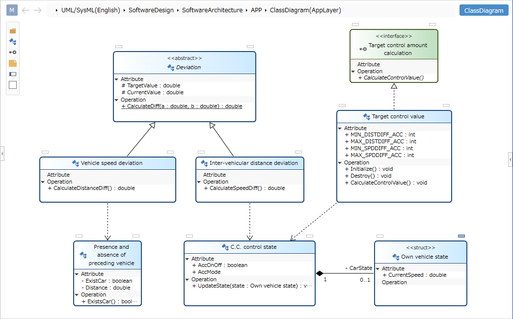
Class diagrams can be used to visualize the static structure of a system.
This page explains the operations for using class diagrams in the following order.
- Place class diagram
- Define the class
- Define relationships
We also provide the following features to assist users in their modeling:
These will also be explained in turn.
- Validate the model
- Set display content
Place the class diagram
To place a class diagram, follow these steps:
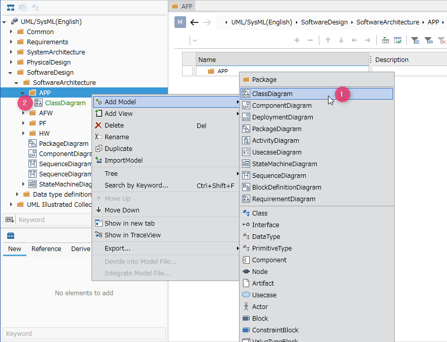
- Select the package in the model navigator and click [Add Model] > [Class Diagram] in the context menu.
- The class diagram is placed in the child element of the selected package.
Define the class
Add class
To add a class, follow these steps:
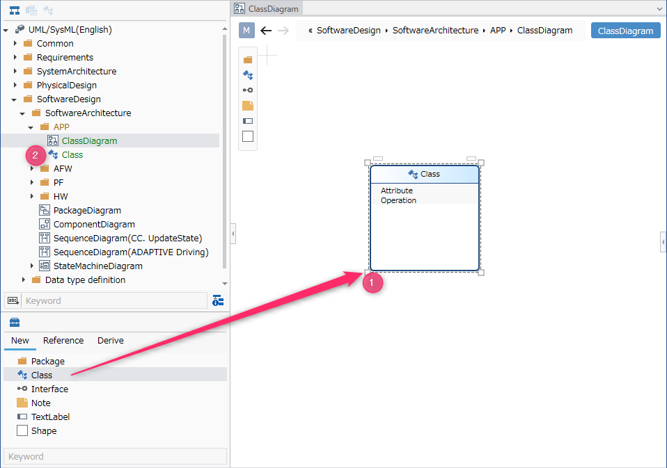
- Drag and drop [Class] from the toolbox onto the displayed class diagram.
- A new class will be added as a sibling element to the displayed class diagram.
In the class diagram, you can place the following elements displayed in the toolbox.
| Icon | Name |
|---|---|
| Package | |
| Class | |
| Interface | |
| Note | |
| Label | |
| Shape |
Add stereotype to class
To add a stereotype, follow these steps:
- Select a class.
- Click the Add button in the Basic information > Stereotype field in the Property Inspector to display the choices.
- Select a stereotype and press the [OK] button to set the stereotype to the class and display the stereotype above the class shape.
Stereotype choices can be defined in the package model's Detail view.
Once you have added a stereotype, you can edit it from the class diagram by following these steps:
- Double-click the stereotype displayed in the class to enter editing status.
- When you change the stereotype and confirm the edit, it will be reflected on the class diagram and the class stereotype will be changed.
Change class to abstract class
To change a class to an abstract class, follow these steps:
- Select a class.
- Check the checkbox in the Properties > Is Abstract field in the Property Inspector to make it an abstract class and display the class name in italics.
If you want to display Japanese class names in italics, please change to a font that supports italics from [Add Shape] > [Text] > [Font Setting] on the ribbon.
If you want to display an existing class on the class diagram, you can display it by dragging and dropping the class on the model navigator onto the class diagram.
Add attributes
To add attributes to a class diagram, follow these steps:
- Click the [+] button in the attribute area of the displayed class shape.
- The attribute is added to the parcel and becomes editable.
- Enter the attribute you want to add according to the text notation described below, confirm, and the attribute will be added.
When you enter an attribute as text on a class diagram, the text is analyzed according to the attribute's notation format and reflected in each field value of the attribute.
Of course, if you change each field value, it will be reflected in the text on the diagram.

Correspondence between attribute text notation format and each field value
Attributes are displayed and parsed as text according to the following format:
- Format
<Attribute> ::= [<Visibility>] [<Derived attribute>] <Attribute name> [':' <Type name>] ['[' <Multiplicity lower limit>'..'< Multiplicity upper limit > ']'] ['=' <Initial value>]- supplement
<Visibility>will be displayed as one of the following:- '+' (Public), '-' (Private), '#' (Protected), '~' (Package/Internal)
- If
<Derived attribute>is true,'/'is displayed. - If
<type name>contains*or&, the string before the corresponding character is treated as thetype name, and the string after the corresponding character is treated as thetype qualifier. To set a type name starting with*or&, please set it in the inspector.
- Example
Attribute name:TargetValue, visibility:Public, derived attribute: true, type:int, type qualifier:*, lower limit of multiplicity:0, upper limit of multiplicity:2, Initial value:-1, the following text will be displayed.
+/TargetValue : int*[0..2]=-1
- supplement
Add operations
To add operations to a class diagram, follow these steps:
- Click the [+] button in the operation area of the displayed class shape.
- The operation is added to the partition and becomes editable.
- Enter the operation to be added according to the text notation described below and confirm, and the operation will be added.
When you enter an operation as text on the class diagram, the text is analyzed according to the operation's notation format and is reflected in each field value of the operation.
Of course, if you change each field value, it will be reflected in the text on the diagram.
Correspondence between operation text notation format and each field value
Operations are displayed and parsed as text according to the following format:
- Format
<operation> ::= [<visibility>] <name of operation> ['(' [<list of parameters>] ')'] [':' [<return type>] ['[' < Multiplicity > ']']- supplement
<Visibility>will be displayed as one of the following:- '+' (Public), '-' (Private), '#' (Protected), '~' (Package/Internal)
<List of parameters>is displayed in the following format.<List of parameters> ::= <parameter> [','<parameter>]*<parameter> ::= [<parameter direction>] <parameter name> ':' <parameter type name> ['['<parameter multiplicity>']'] ['=' <parameter Initial value>]- If
<parameter type name>contains*or&, the string before the corresponding character is treated as thetype name, and the string after the corresponding character is treated as thetype qualifier. . To set a type name starting with*or&, please set it in the inspector. - One of the following will be displayed for
<parameter direction>.in,out,inout
- If
- Example
Operation name:Drive, visibility:Public
Parameter 1 name:miles, type:int, type qualifier:&, initial value:100, multiplicity:1..*
Parameter 2 name:speed, type:int, direction:out
In this case, the following text will be displayed.
+ Drive(miles : int&[1..*]=100, out speed : int)
- supplement
Define the relationship
To define an association, follow these steps:
- Move the pointer over the class you want to associate.
- Drag the [▲] icons that appear on all sides of the class and drop them onto the other class you want to associate.
- A list of relationships that can be added will be displayed. Select the relationship you want to add, and the selected relationship will be added.
The following relationships are available in class diagrams:
| Icon | Name |
|---|---|
| Depends | |
| Relationship | |
| Related (unidirectional) | |
| Owned | |
| Aggregation | |
| Inheritance | |
| Realization |
Edit related multiplicity
- Select an association.
- Double-click the grayed-out [*] to enter editing mode.
- Enter the multiplicity you want to set, the multiplicity will be set for the association, and the multiplicity will be displayed for the association in the class diagram.
Edit related end name
- Select an association.
- Double-click the grayed out [-] to enter editing mode.
- Enter the relationship end name you want to set, the relationship end name will be set in the relationship, and the relationship end name will be displayed in the relationship in the class diagram.
Add stereotypes to associations
To add a stereotype, follow these steps:
- Select an association.
- Double-click the grayed-out [<<stereotype>>] to enter editing mode.
- Enter the stereotype you want to set, and the stereotype will be displayed in the association in the class diagram, and the stereotype will be set in the association.
Validate the model
The contents verified in the class diagram are as follows.
- Is there a circular inheritance relationship between classes and interfaces?
- Is there a class set as the inheritance source of the interface?
- Is there a subclass set for the final class?
To validate your model, follow these steps:
- Run UML > Validation > Check Consistency from the ribbon.
- If all models under the project are in an inconsistent state, an error will be displayed.
Click the [Home] > [Model] > [Check Error] button on the ribbon to perform validation on all models in addition to the standard validation.
Also, when a new inheritance relationship is added on the class diagram, the relationship between classes will be checked in real time based on the added inheritance relationship.
Set display content
You can display only the information of interest in class diagrams without changing the model.
To configure the display of operation parameters, follow these steps:
- Display the class diagram whose display you want to switch.
- Toggle the check mark on the parameter checkbox in the [Operations] group on the [UML Diagram] tab of the Inspector.
You can switch the display of the following elements in the class diagram.
| Category | Element |
|---|---|
| Common | Stereotype |
| Attributes | Visibility |
| Type | |
| Multiplicity | |
| Default Value | |
| Operations | Visibility |
| Return type | |
| Command Parameter | |
| Parameter type | |
| Parameter direction | |
| Initial values of parameters | |
| Relationship | Visibility |
Restrictions
- Italic cannot be specified as type name style. If the type is abstract, it is automatically displayed in italics.
- If the type name font does not support italics, it will not be possible to express whether it is an abstract type on the diagram. Please check in the sub editor or inspector.
- Examples of unsupported fonts: Meiryo (default font)
- Underline cannot be specified in attribute style. If the attribute is a static attribute, it is automatically underlined.
- Italic cannot be specified in the operation style. If the operation is an abstract operation, it is automatically displayed in italics.
- Underline cannot be specified in operation style. If the operation is a static operation, it is automatically underlined.
- If you want to specify the type specified in an attribute or operation by text editing, it must be defined in advance. It will not be added automatically.
- If the name of a type used in an attribute or operation contains the following characters used in the syntax of an attribute or operation, they may be incorrectly interpreted and reflected in the model when editing text.
- "," (half-width comma), ")" (close half-width parenthesis), "]" (close half-width parenthesis), "=" (half-width equal), "*" (half-width asterisk), "&" (half-width ampersand)
- Lollipop display of the interface is not possible.
- If you want to change the type of relationship (dependency, ownership, aggregation, etc.) between classes that have been added, you will need to re-create them.
- Note anchors cannot be attached to class attributes, operation elements, or connectors.
- Ownership relationships between packages and classes cannot be expressed in connectors.
- The following limitations remain, but problems can be detected using the check function.
- You can specify a class as the inheritance source of an interface.
- You can define circular inheritance.
- Subclasses can be defined even in the final class.
- Related classes cannot be defined.
- Inner classes cannot be represented.