Component Diagram
Overview
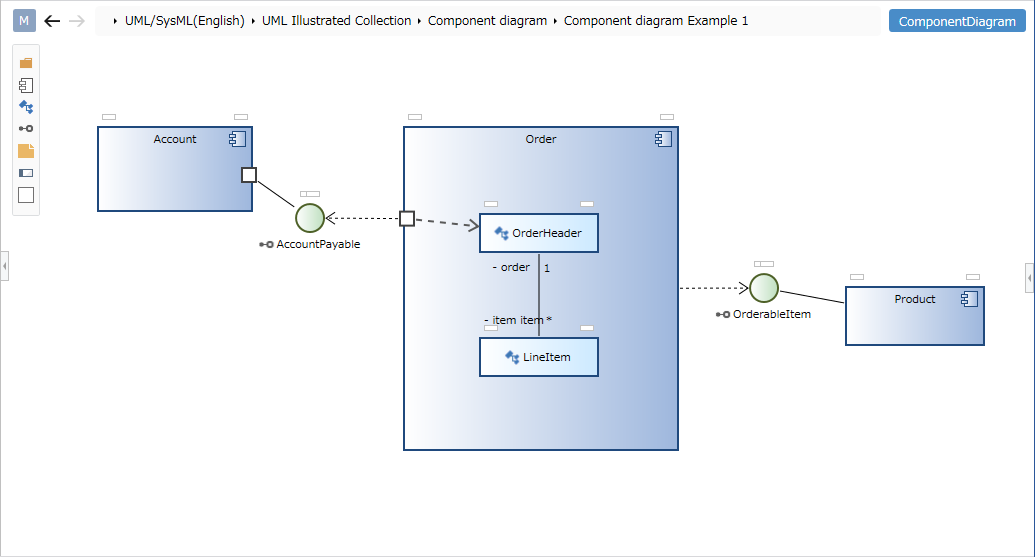
Component diagrams can be used to describe the internal structure of components and the relationships between them.
This page explains the operations for using component diagrams in the following order.
- Place component diagram
- Define the component
- Define relationships
We also provide the following features to assist users in their modeling:
These will also be explained in turn.
- Set display content
Place component diagram
To place a component diagram, follow these steps:

- Select the package in the model navigator and click [Add Model] > [Component Diagram] in the context menu.
- The component diagram is placed in the child element of the selected package.
Define the component
To define a component, follow these steps:
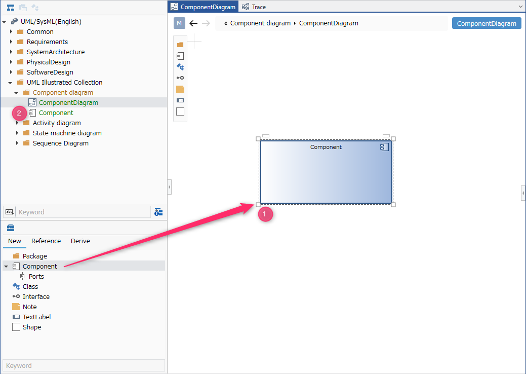
- Drag and drop [Component] from the toolbox onto the displayed component diagram.
- The component is placed in the sibling element of the displayed component diagram.
You can add the following elements displayed in the toolbox to the component diagram.
| Icon | Name |
|---|---|
| Package | |
| Component | |
| Port | |
| Class | |
| Interface | |
| Note | |
| Label | |
| Shape |
Place ports as port shapes in the following elements:
- Component
Add stereotypes to components
To add a stereotype, follow these steps:
- Select a component.
- Click the Add button in the Basic information > Stereotype field in the Property Inspector to display the choices.
- Select a stereotype and press the [OK] button to set the stereotype to the component and display the stereotype at the top of the shape.
Stereotype choices can be defined in the package model's Detail view.
Once you have added a stereotype, you can edit it from the component diagram by following these steps:
- Double-click the stereotype displayed in the component to enter editing state.
- If you change the stereotype and confirm the edit, it will be reflected on the component diagram and the component stereotype will be changed.
- If you want to display an existing component on the component diagram, you can display it by dragging and dropping the component on the model navigator onto the component diagram.
- You can define the internal structure of a component by dragging and dropping components and classes onto the component shape on the diagram.
Components and classes defined as internal structures are added as child elements of the component.
Define the relationship
To define an association, follow these steps:
- Move the pointer over the component you want to associate.
- Drag the [▲] icons that appear on all sides of the component and drop them onto the interface you want to associate.
- A list of relationships that can be added will be displayed. Select the relationship you want to add, and the selected relationship will be added.
The following relationships are available in component diagrams:
| Icon | Name |
|---|---|
| Depends | |
| Relationship | |
| Use | |
| Related (unidirectional) | |
| Owned | |
| Aggregation | |
| Inheritance | |
| Realization |
Add stereotypes to associations
To add a stereotype, follow these steps:
- Select an association.
- Double-click the grayed-out [<<stereotype>>] to enter editing mode.
- Enter the stereotype you want to set, the stereotype will be set to the relationship, and the stereotype will be displayed in the relationship in the component diagram.
You can also define relationships for ports placed as child elements of components.
Component diagrams can also define relationships between classes.
For more information, see Class Diagram.
Set display content
You can display only the information of interest in component diagrams without changing the model.
To configure what the visibility of a relationship displays, follow these steps:
- Display the component diagram whose display you want to switch.
- Toggle the check mark on the visibility checkbox in the [Relationship] group on the [UML Diagram] tab in the Inspector.
Restrictions
- Interfaces are represented differently from the UML standard (classes cannot be displayed and are represented as circles).
- Parts cannot be defined.
- The connection between ports is different from the UML standard, and it is also possible to connect directly with a connector without going through an interface.