D3. Designing the Architecture
Software architecture design allows for the following designs:
- Component configuration and relationships at the architectural level
- Assignment of software requirements to components and specifications for each component
- Interfaces between components
- Assignment of execution units (tasks/processes/interrupts, etc.) and interface functions
- Dynamic behavior using sequence diagrams, state machine diagrams, and DFDs
- Resource analysis such as CPU load and ROM/RAM size
- Impact analysis based on interface relationships
The following sections describe the design screen images, the models to be edited, and the views and extension functions used for each use case.
| ユースケース | 画面イメージ | モデルとビュー | 説明 |
|---|---|---|---|
| D3.1. Designing Component Configuration | 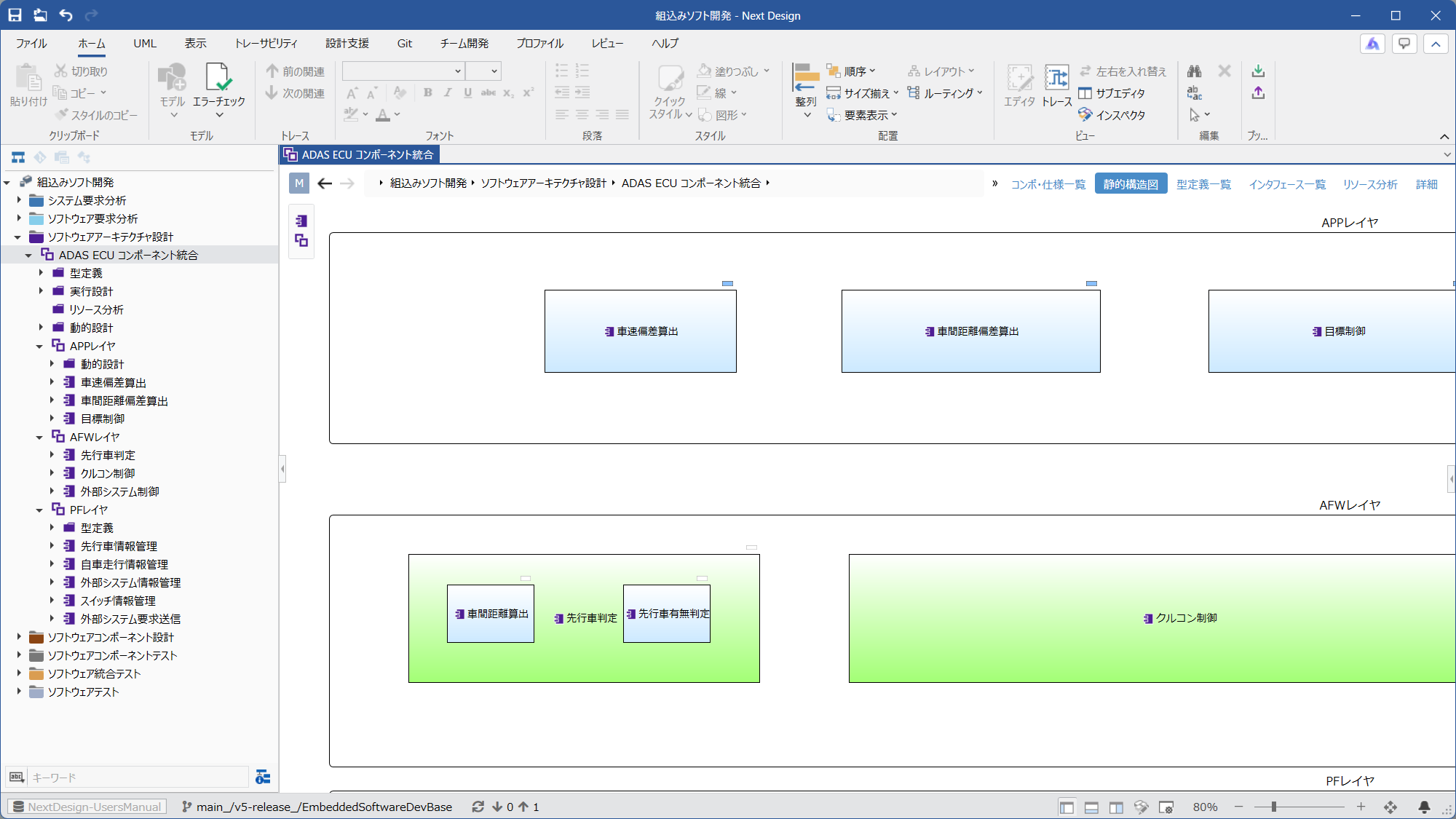 | Ⓜ Main Editor • Model: [SoftwareArchitectureDesignGroup] • View: [StaticStructureDiagram] Ⓢ Sub Editor • None | Components can be placed within groups such as layers. Grouping and component hierarchy are possible. |
| D3.2. Deriving Component Specifications | |||
| └ D3.2.1. Deriving Component Specifications from Software Requirements | 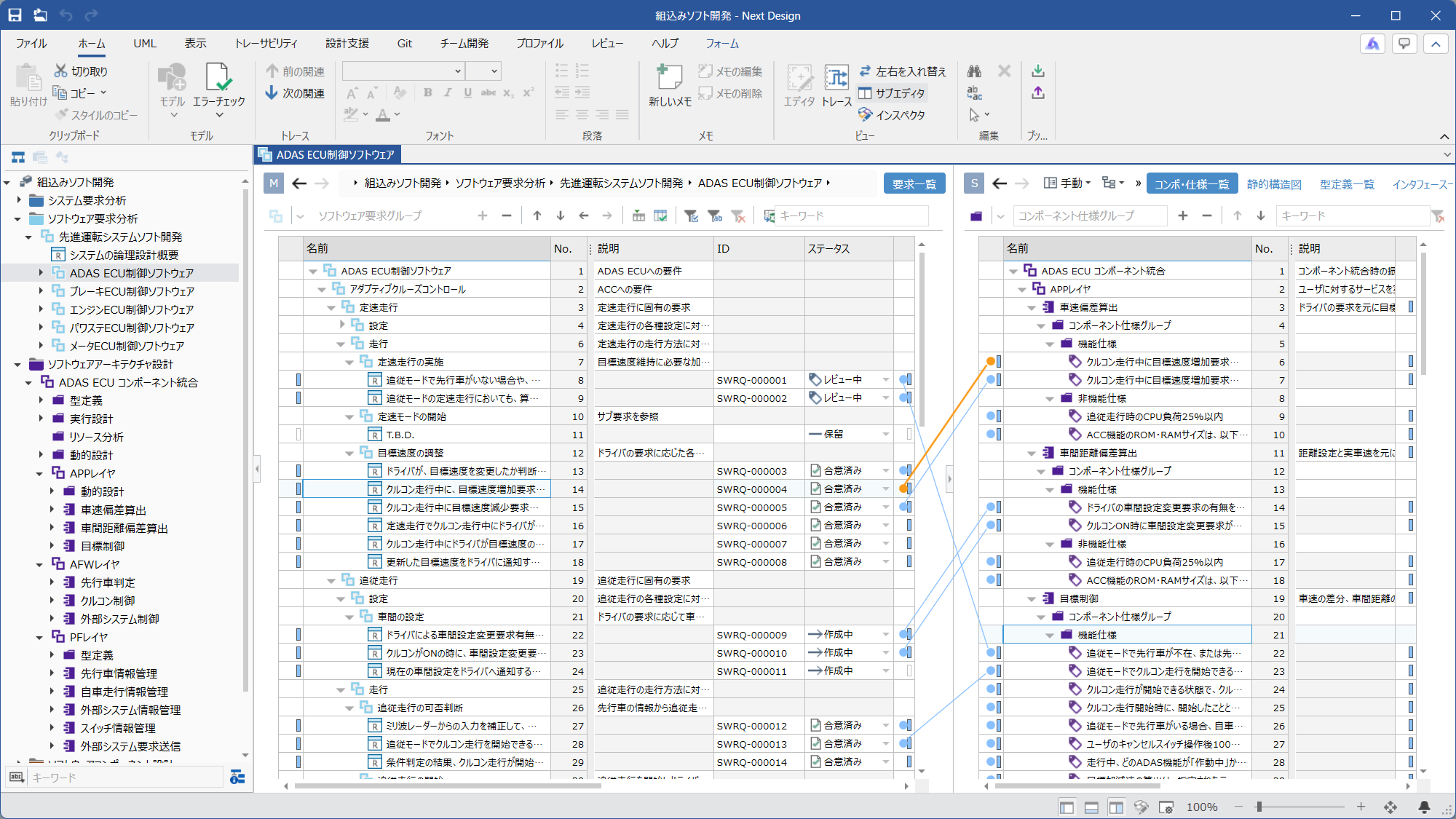 | Ⓜ Main Editor • Model: [SoftwareRequirementAnalysis]/[SoftwareRequirementGroup] • View: [Requirement list] Ⓢ Sub Editor • Display Mode: [Manual] • Model: [SoftwareArchitectureDesignGroup] • View: [Component_SpecificationList] | Two-screen configuration for deriving component-specific specifications from [Software requirements]. You can assign [Software requirements] to a component by deriving [ComponentSpecification]. You can also add [ComponentSpecification] individually and then associate it with [Software requirements]. |
| └ D3.2.2. Distributing component specifications to subcomponents | 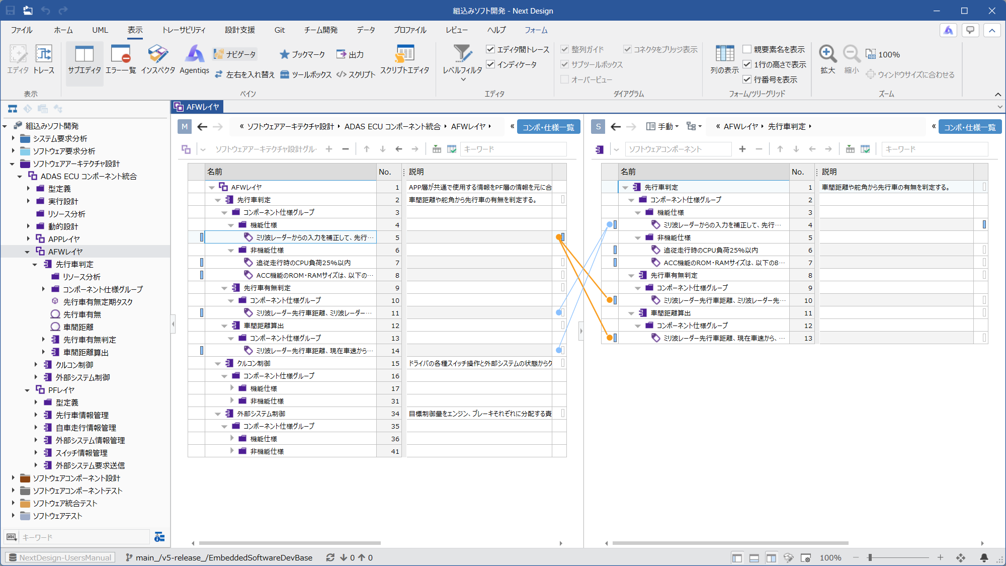 | Ⓜ Main Editor • Model: Either [SoftwareArchitectureDesignGroup] or [SoftwareComponent] • View: [Component_SpecificationList] Ⓢ Sub Editor • Display Mode: [Manual] • Model: Either [SoftwareArchitectureDesignGroup] or [SoftwareComponent] • View: [Component_SpecificationList] | The higher-level [ComponentSpecification] can be divided and assigned according to the responsibilities of the subcomponents. By establishing a derivation relationship between the higher-level [ComponentSpecification] and the subcomponent's [ComponentSpecification], you can track the correspondence with the higher-level specification. |
| D3.3. Designing Interfaces Between Components | |||
| └ D3.3.1. Designing Types Required for Interfaces | 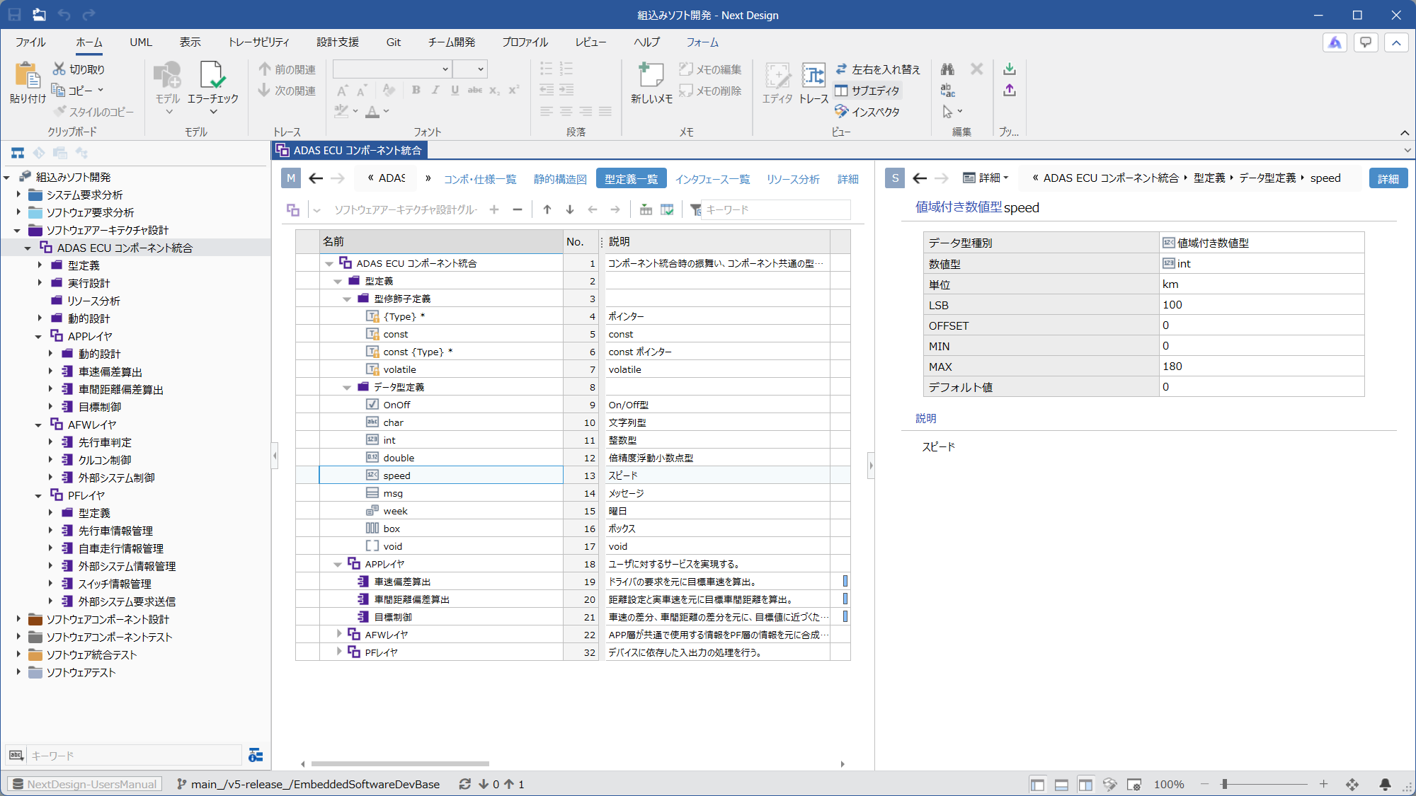 | Ⓜ Main Editor • Model: [SoftwareArchitectureDesignGroup] • View: [TypeDefinitionList] Ⓢ Sub Editor • Display Mode: [Detail] | You can add type definitions for each group and component. |
| └ D3.3.2. Designing Component Interfaces (Functions/Data) | 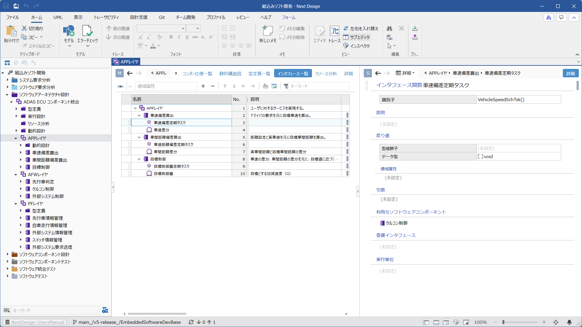 | Ⓜ Main Editor • Model: [SoftwareArchitectureDesignGroup] • View: [Interface List] Ⓢ Sub Editor • Display Mode: [Detail] | You can add interface functions and interface data for each component. |
| └ D3.3.3. Associating Interfaces Between Components | 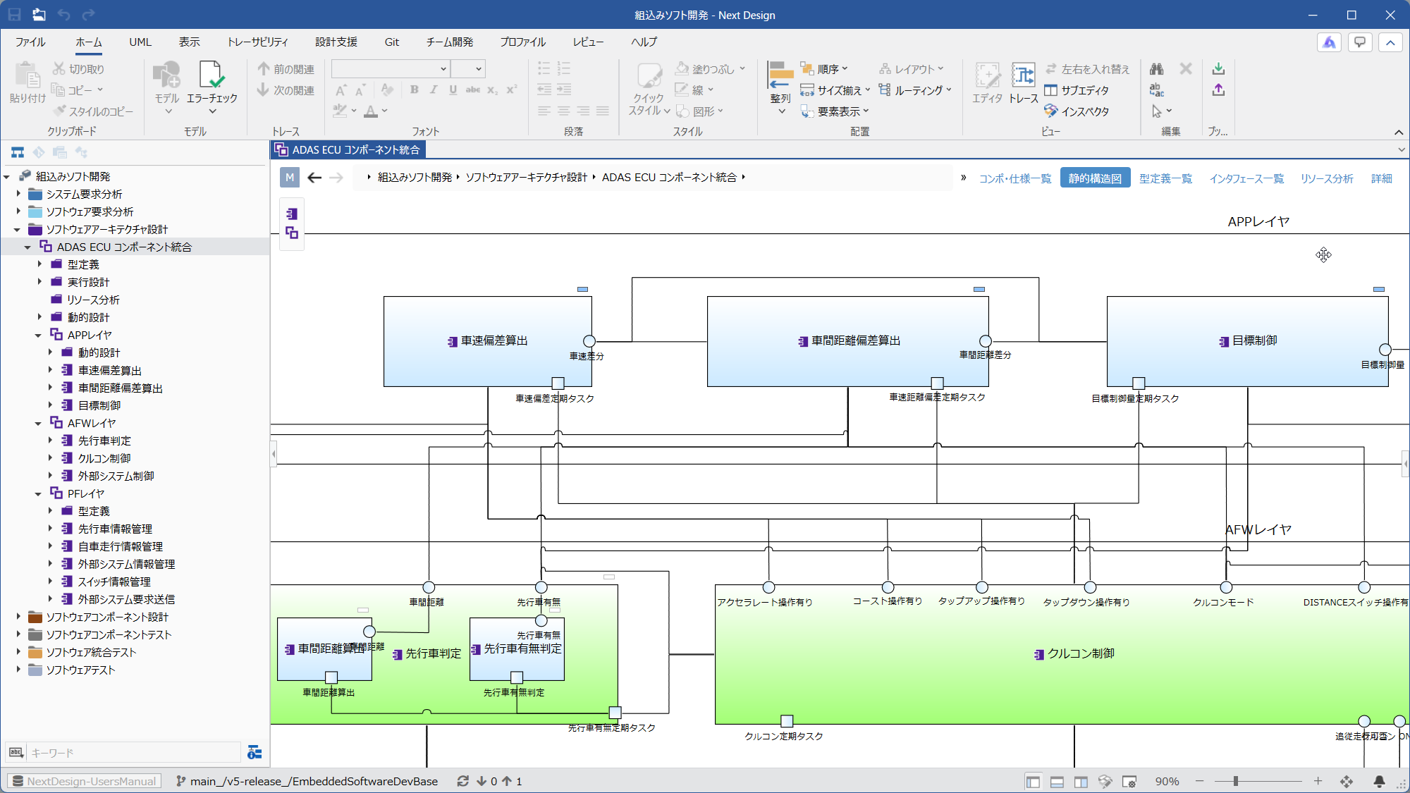 | Ⓜ Main Editor • Model: [SoftwareArchitectureDesignGroup] or [SoftwareComponent] • View: [StaticStructureDiagram] Ⓢ Sub Editor • None | Interfaces can be associated by connecting the interfaces of components with connectors. |
| D3.4. Dynamic Design | |||
| └ D3.4.1. Designing Execution Timing | 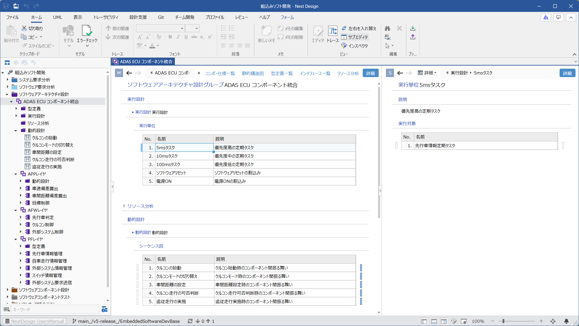 | Ⓜ Main Editor • Model: [SoftwareArchitectureDesignGroup], [SoftwareComponent] • View: [Detail] Ⓢ Sub Editor • Display Mode: [Detail] | You can design execution units such as periodic tasks and interrupt events for each group and component. |
| └ D3.4.2. Designing Architecture-Level Behavior | 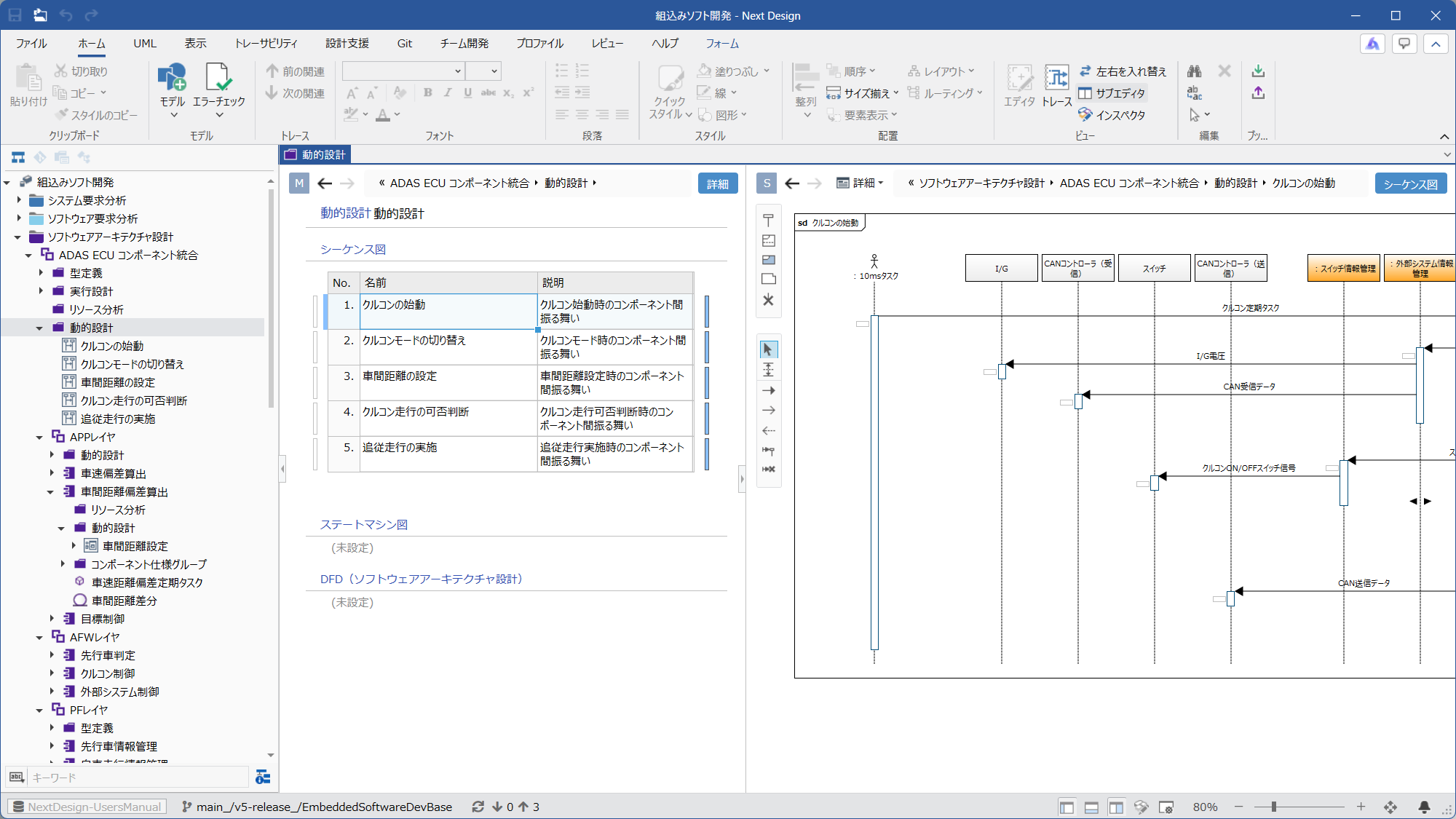 | Ⓜ Main Editor • Model: [DynamicDesign] • View: [Detail] Ⓢ Sub Editor • Display Mode: [Detail] • View: One of [Sequence Diagram], [State Machine Diagram], [State transition table], or [DFD] | Adding a [DynamicDesign] model to a group or component enables dynamic design using the optimal design methodology. |
| D3.5. Performing Resource Analysis | 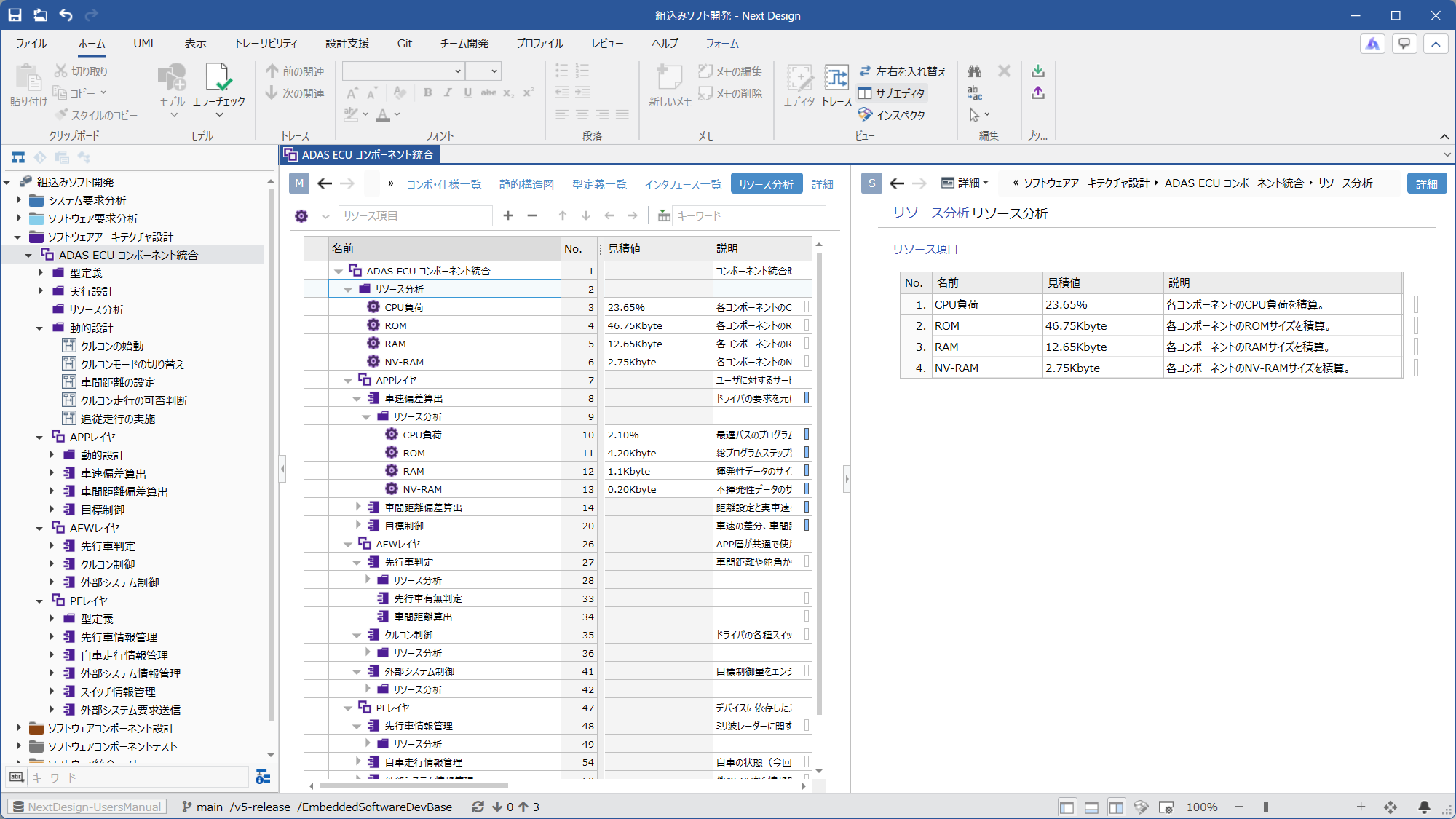 | Ⓜ Main Editor • Model: [SoftwareArchitectureDesignGroup] • View: [ResourceAnalysis] Ⓢ Sub Editor • Display Mode: [Detail] | By adding a [ResourceAnalysis] model to a group or component, you can include estimated values for CPU load and ROM/RAM size. |
| D3.6. Analyzing the Scope of Impact | 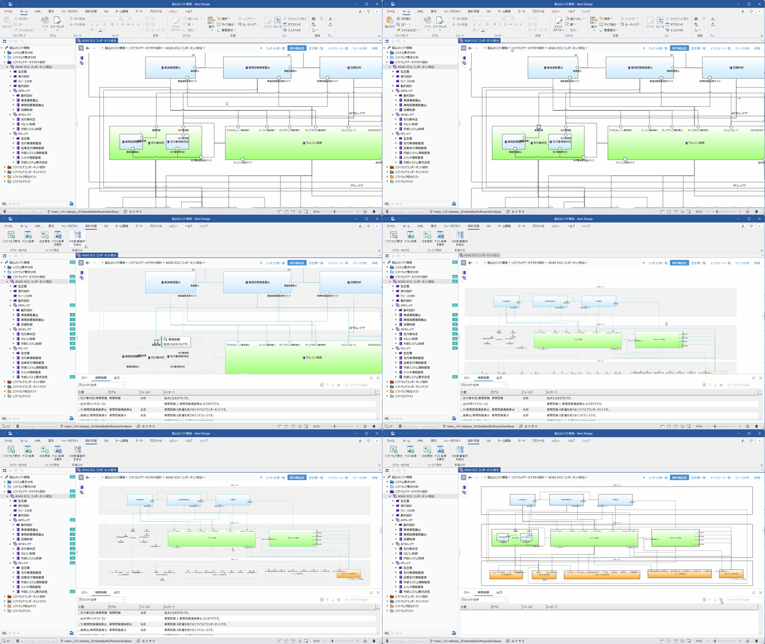 | Ⓜ Main Editor • Model: [SoftwareArchitectureDesignGroup] or [SoftwareComponent] • View: [StaticStructureDiagram] Ⓢ Sub Editor • None | By selecting one interface or component on the diagram and clicking the [Design Support] > [Impact Analysis] > [Extract IF Influence] button on the ribbon tab, the extension function can determine the interfaces' related targets. |