D4. Detailed Design of Components and Units
In software component design, the following designs can be made targeting the terminal components and units, which consist only of the smallest implementation units.
- Unit configuration and relationships using static structural diagrams at the component level
- Unit specifications according to component specifications
- Interfaces between and within units
- Dynamic behavior using sequence diagrams, state machine diagrams, DFDs, and flowcharts
Below, for each use case, we will describe the screen image during design, the model to be edited, and the views used.
Note that below, software architecture design will be referred to as the "higher-level process," and software component design as the "main process."
Components of the higher-level process and components of the main process
- In software component design, the components of the main process are designed targeting the end-level components among the hierarchical components established in the higher-level process.
- Components of the higher-level process and components of the main process are treated as separate models, and their correspondence is represented by derivation relationships.
| ユースケース | 画面イメージ | モデルとビュー | 説明 |
|---|---|---|---|
| D4.1. Deriving Components from Architectural Design | 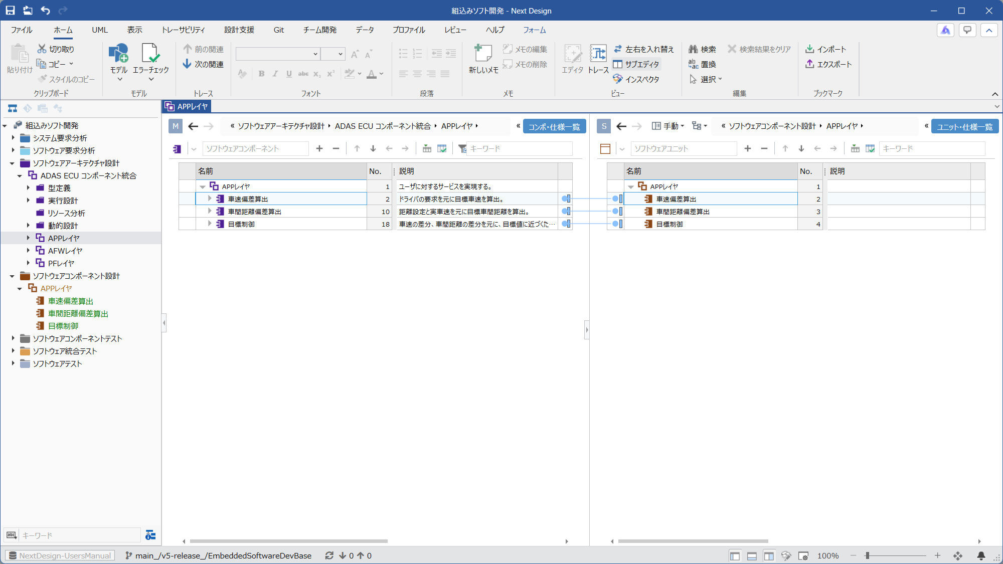 | Ⓜ Main Editor • Model: [SoftwareArchitectureDesignGroup] • View: [Component_SpecificationList] Ⓢ Sub Editor • Display Mode: [Manual] • Model: [SoftwareComponentDesignGroup] • View: [Unit_SpecificationsList] | By adding [SoftwareComponentDesignGroup], you can derive the [SoftwareComponent] of this process from the [SoftwareComponent] of the higher-level process using a two-screen configuration. You can also add [SoftwareComponent] individually and then associate it with the [SoftwareComponent] of the higher-level process. |
| D4.2. Design the units that make up each component | 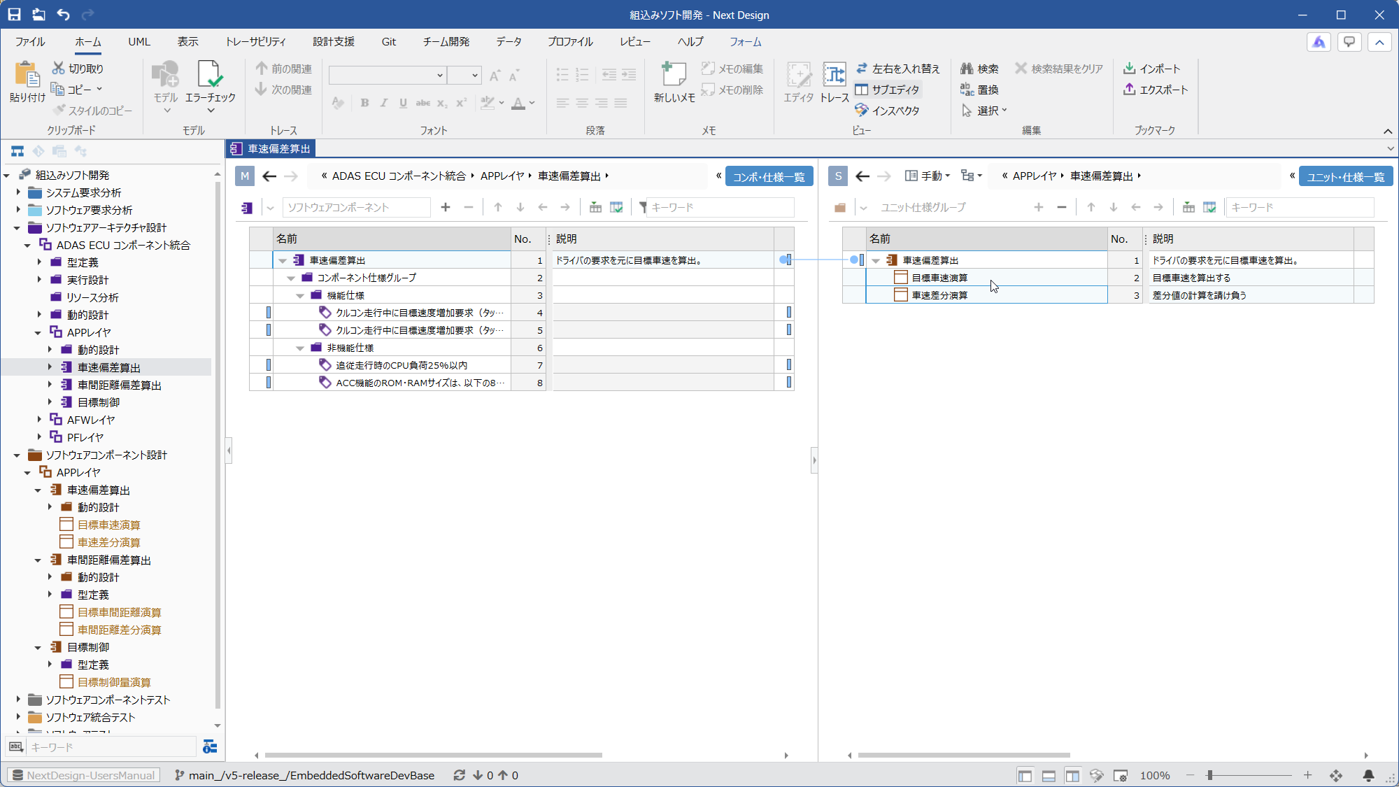 | Ⓜ Main Editor • Model: [SoftwareArchitectureDesignGroup] or [SoftwareComponent] from a higher-level process • View: [Component_SpecificationList] Ⓢ Sub Editor • Display Mode: [Manual] • Model: [SoftwareComponentDesignGroup] or [SoftwareComponent] from this process • View: [Unit_SpecificationsList] | You can also design the units that make up a component in the sub-editor. Units cannot be hierarchical. |
| D4.3. Deriving Unit Specifications from Architecture Design | 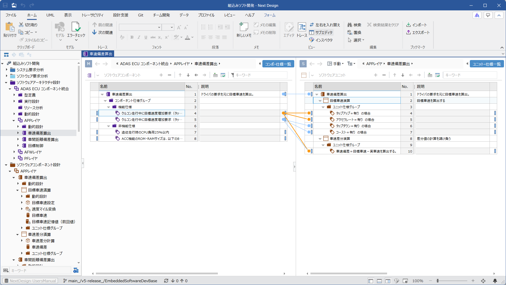 | Ⓜ Main Editor • Model: [SoftwareArchitectureDesignGroup] or [SoftwareComponent] from a higher-level process • View: [Component_SpecificationList] Ⓢ Sub Editor • Display Mode: [Manual] • Model: [SoftwareComponentDesignGroup] or [SoftwareComponent] from this process • View: [Unit_SpecificationsList] | This two-screen configuration allows you to derive the [UnitSpecification] from the [ComponentSpecification] of a higher-level process. You can also add [UnitSpecification] individually and then associate it with the [ComponentSpecification] of the higher-level process. |
| D4.4. Designing the unit interface | |||
| └ D4.4.1. Designing the types required for the interface | 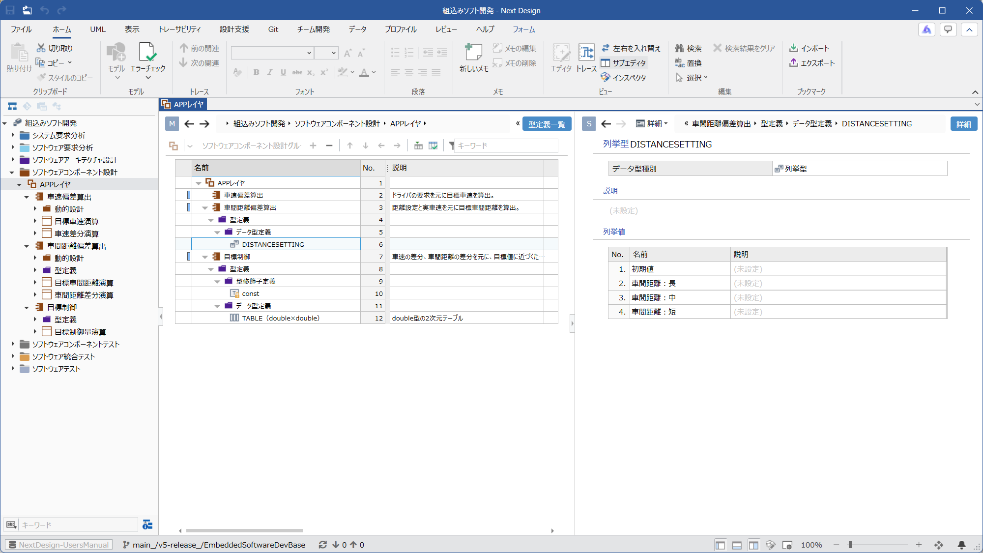 | Ⓜ Main Editor • Model: [SoftwareComponentDesignGroup] or [SoftwareComponent] of this process • View: [TypeDefinitionList] Ⓢ Sub Editor • Display Mode: [Detail] | You can add type definitions for each component. |
| └ D4.4.2. Deriving Unit Interfaces from Architecture Design | 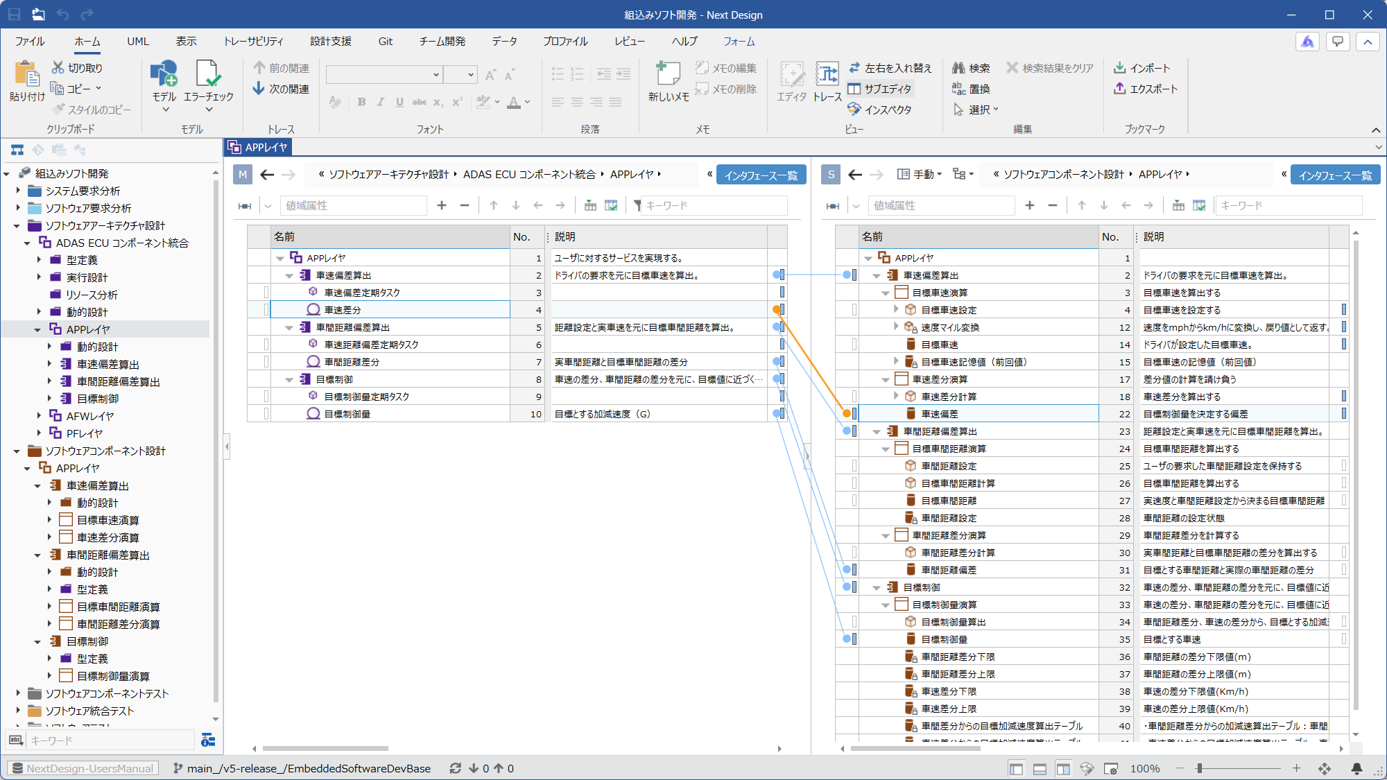 | Ⓜ Main Editor • Model: [SoftwareArchitectureDesignGroup] or [SoftwareComponent] from a higher-level process • View: [Interface List] Ⓢ Sub Editor • Display Mode: [Manual] • Model: [SoftwareComponentDesignGroup] or [SoftwareComponent] from this process • View: [Interface List] | Two-screen configuration for [InterfaceFunction] and [InterfaceData] from higher-level processes. You can derive the interface of the unit in this process from this. You can also add the interface of this process individually and then associate it with the interface of the higher-level process. |
| └ D4.4.3. Designing the unit interface | 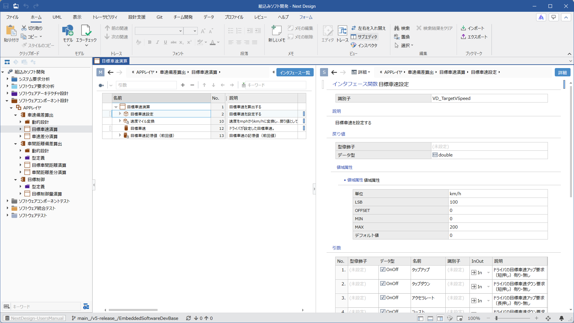 | ⓂMain Editor • Model: [SoftwareComponentDesignGroup], or either [SoftwareComponent] or [SoftwareUnit] of this process • View: [Interface List] ⓈSub Editor • Display Mode: [Detail] | You can add interface functions, internal functions, interface data, and internal data for each unit and design their details. |
| └ D4.4.4. Associating Interfaces Between Units | 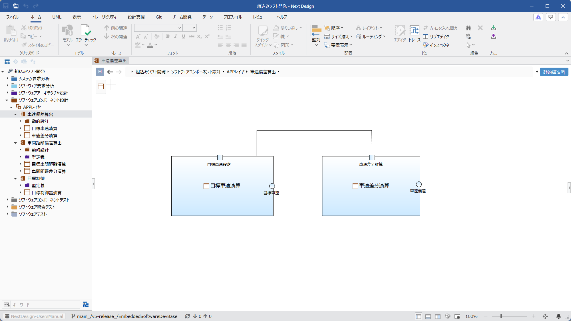 | Ⓜ Main Editor • Model: [SoftwareComponent] of this process • View: [StaticStructureDiagram] Ⓢ Sub Editor • None | Interfaces can be associated by connecting the interfaces of units with connectors. |
| D4.5. Performing Dynamic Design | |||
| └ D4.5.1. Designing the Internal Behavior of Components | 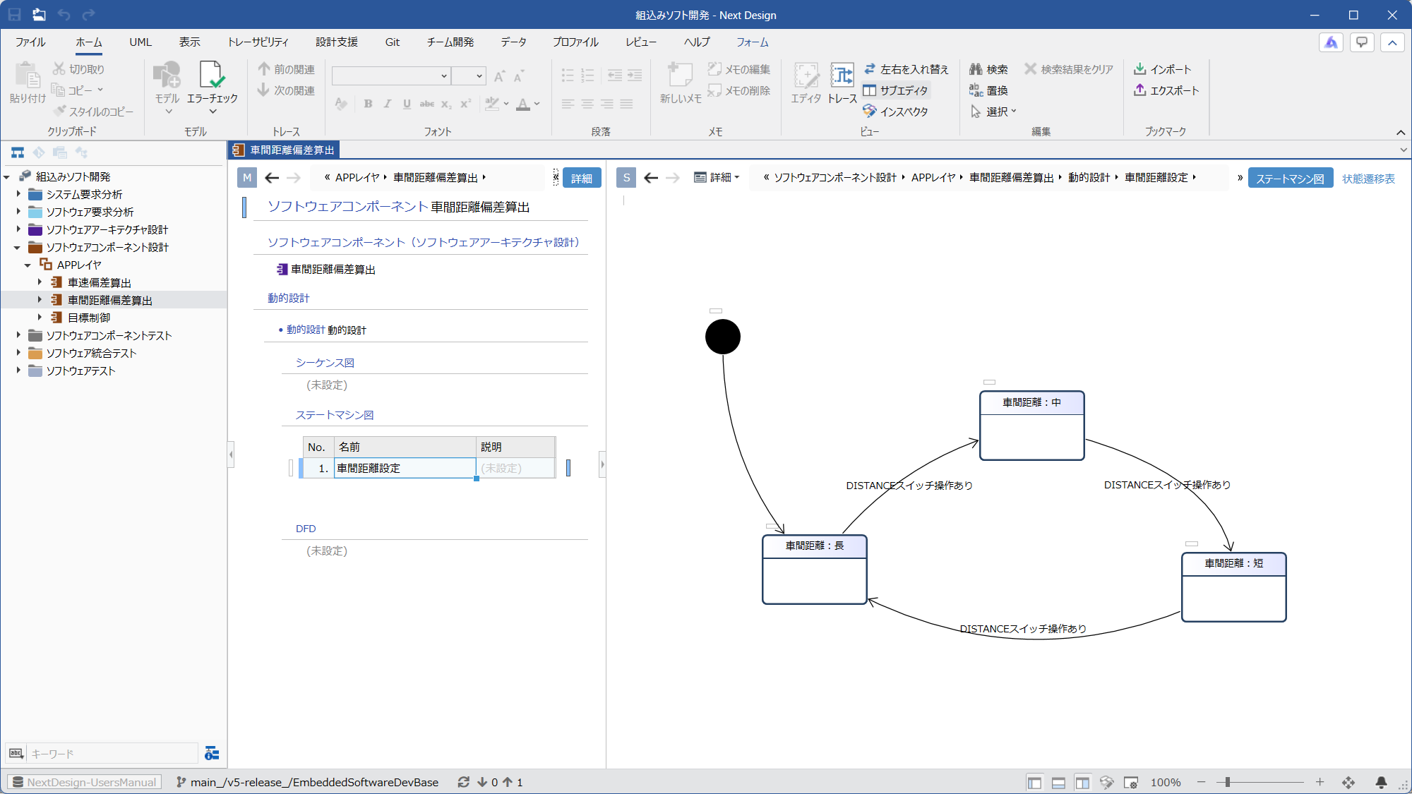 | Ⓜ Main Editor • Model: [SoftwareComponent] of this process • View: [Detail] Ⓢ Sub Editor • Display Mode: [Detail] • View: One of [Sequence Diagram], [State Machine Diagram], [State transition table], or [DFD] | Adding a [DynamicDesign] model to a component allows you to perform dynamic design using the optimal design method. |
| └ D4.5.2. Designing the behavior of units | 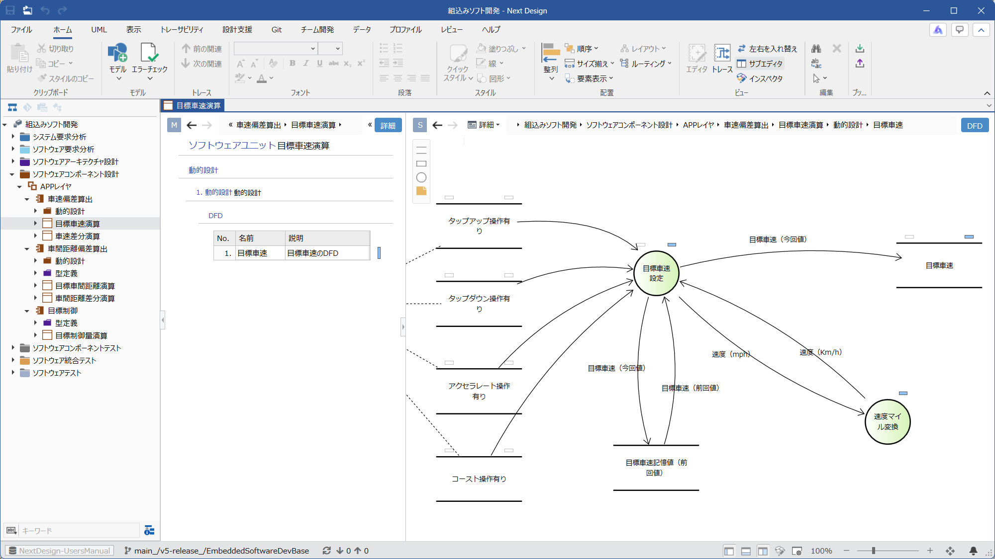 | Ⓜ Main Editor • Model: [SoftwareUnit] • View: [Detail] Ⓢ Sub Editor • Display Mode: [Detail] • View: [DFD] | By adding a [DynamicDesign] model to a unit, you can perform dynamic design using DFD. |
| └ D4.5.3. Designing the Behavior of Interface Functions and Internal Functions | 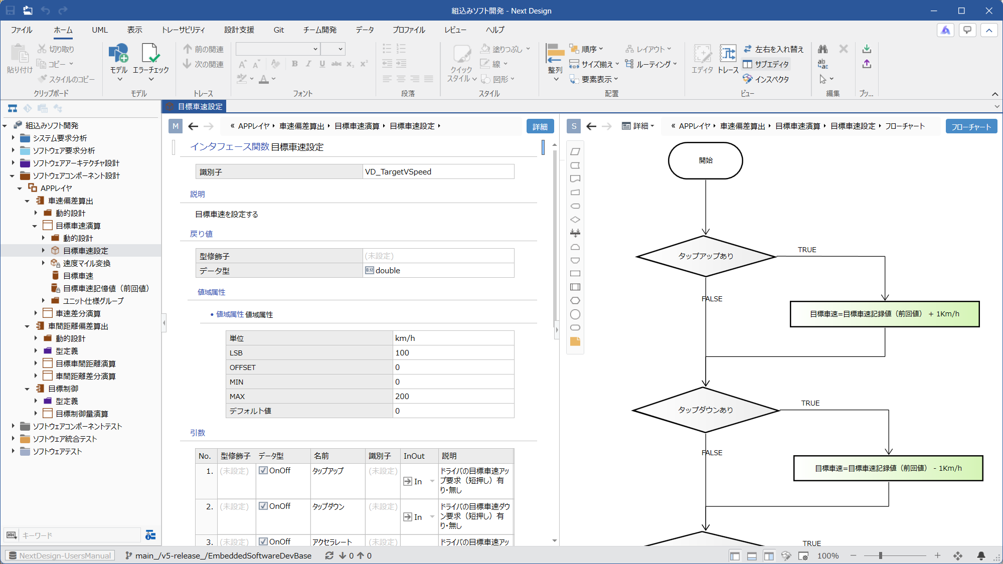 | Ⓜ Main Editor • Model: Either [InterfaceFunction] or [InternalFunction] from this process • View: [Detail] Ⓢ Sub Editor • Display Mode: [Detail] • View: [Flow Chart] | Dynamic design of interface functions and internal functions can be done using flowcharts. |