Feature model definition
Overview
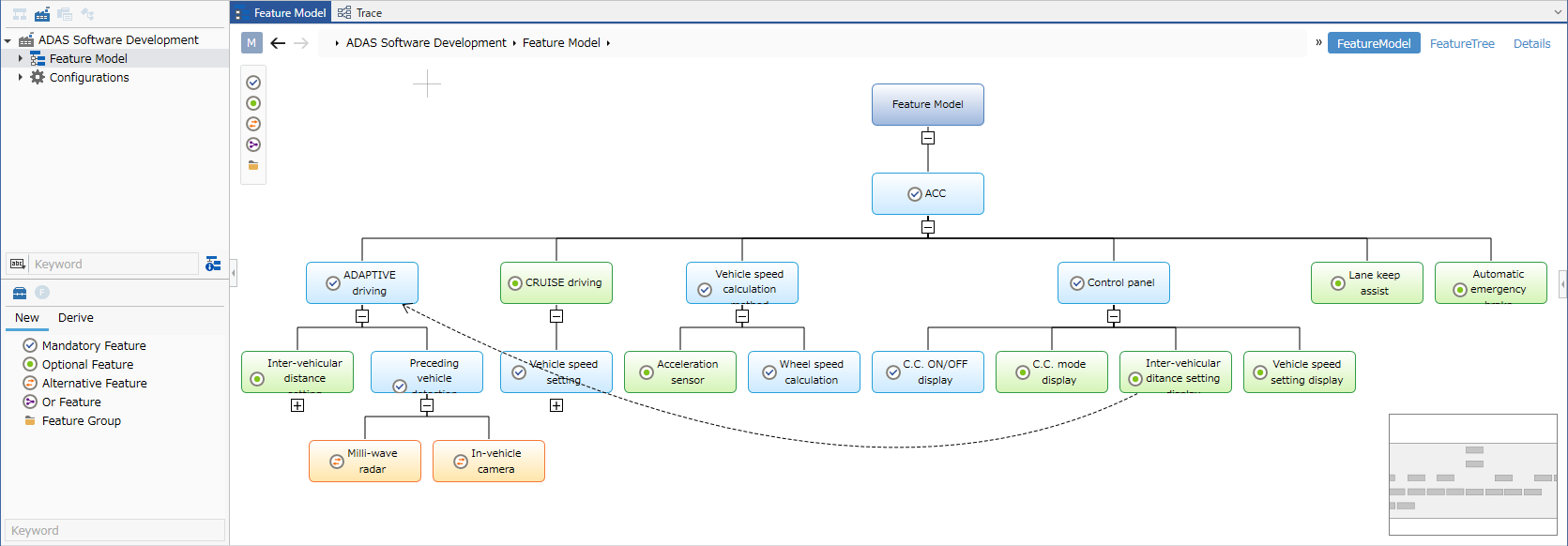
Next Design allows you to define the structure of a feature model in a tree diagram format and define constraints between features.
The following describes the steps to define a feature model in the following order:
- Start product line development
- Define the feature model structure
- Add constraints between features
- Check the consistency of the feature model
Start product line development
To apply product line development to a project, follow these steps:
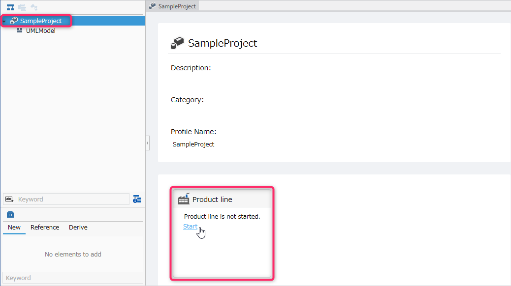
- Select the root project in [Model Navigator].
- Click the [Start] link for the product line from the project screen.
- This allows you to use the features that support product line development.
- Once you start product line development and save the project, you cannot stop product line development.
Define the structure of the feature model
Switch to the feature editor
Feature models are created and edited in the feature editor. To switch to the feature editor, follow the steps below.
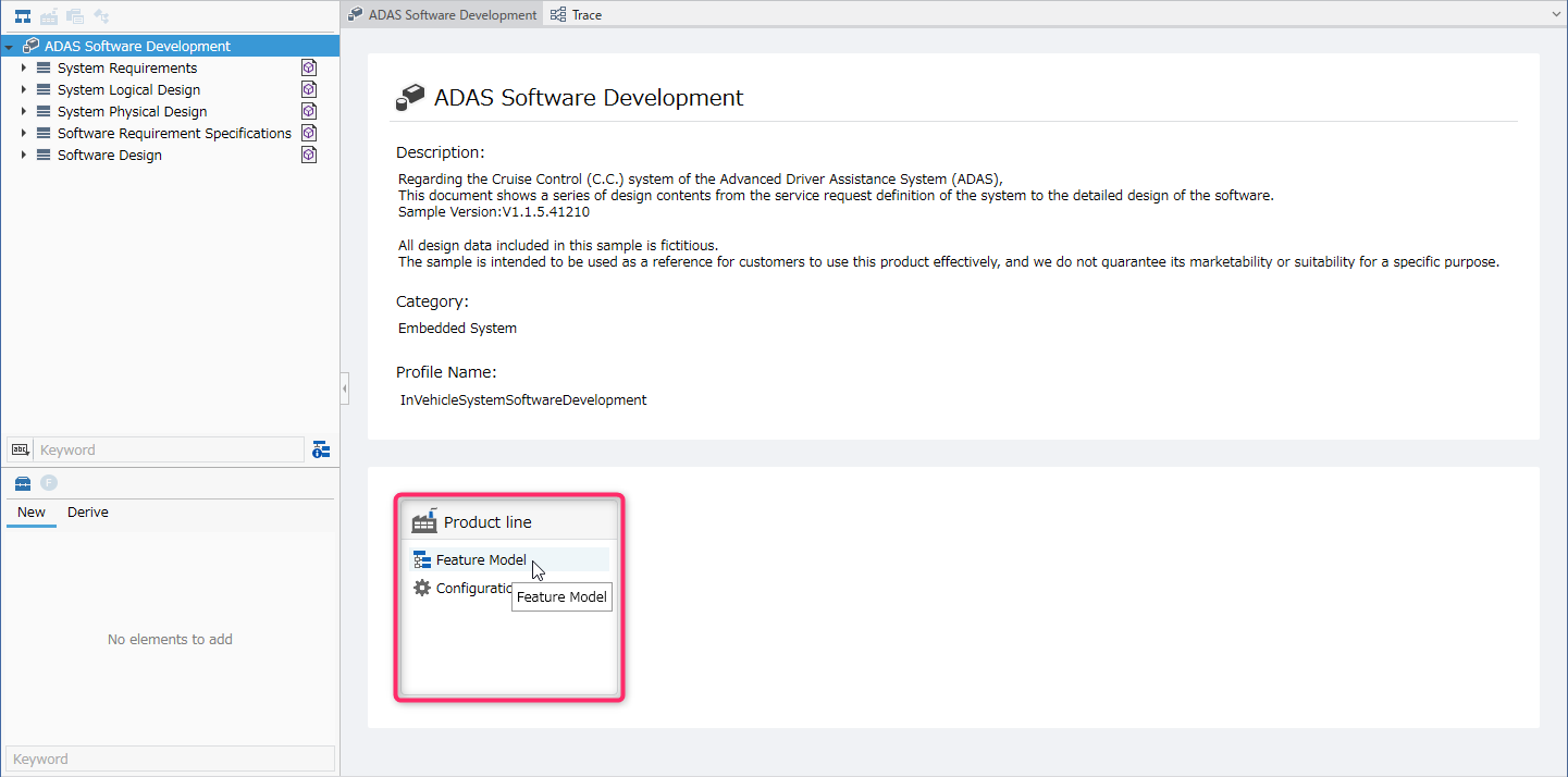
- Click [Feature Model] displayed in the product line on the project screen to switch to the feature editor.
You can also switch to the feature editor by following the steps below.
- Switch the navigator to [Product line navigator].
- Select [Feature Model] directly under the project.
Editing a feature model
To add a feature using the feature editor, follow the steps below, just like editing a model in the tree diagram.
- Select a feature type from the toolbox and drag and drop it onto the feature model.
| Feature type | Description |
|---|---|
| Mandatory Feature | A feature that must be selected when a parent feature is selected |
| Optional Feature | A feature that can be selected optionally when a parent feature is selected |
| Alternative Feature | A feature that must be selected from among sibling alternative features when a parent feature is selected |
| Or Feature | A feature that must be selected from among sibling logical OR features when a parent feature is selected |
| Feature Group | A node in a tree structure that represents the concept of grouping multiple features |
You can also add a feature by following the steps below.
- Select the parent feature in the feature editor.
- Click [Product Line] > [Feature] > [Create] from the ribbon and select the type of feature you want to add.
- You cannot add subfeatures below the 16th level in the Feature Tree view of the Feature Editor. Also, even if there are subfeatures below the 16th level, they are not displayed. If you want to display or add subfeatures below the 16th level, use the Feature Model view of the Feature Editor or the Product Line Navigator.
Changing the feature type
To change the type of an existing feature, follow the steps below.
- Select the target feature.
- Change the feature type by doing one of the following:
- Right-click the selected feature and select the type from Convert View in the context menu.
- Click Product Line > Feature > Convert View from the ribbon and select the feature type.
Setting the initial selection state of a feature
To change the initial state of a feature for a product to selected during configuration, change the property as follows.
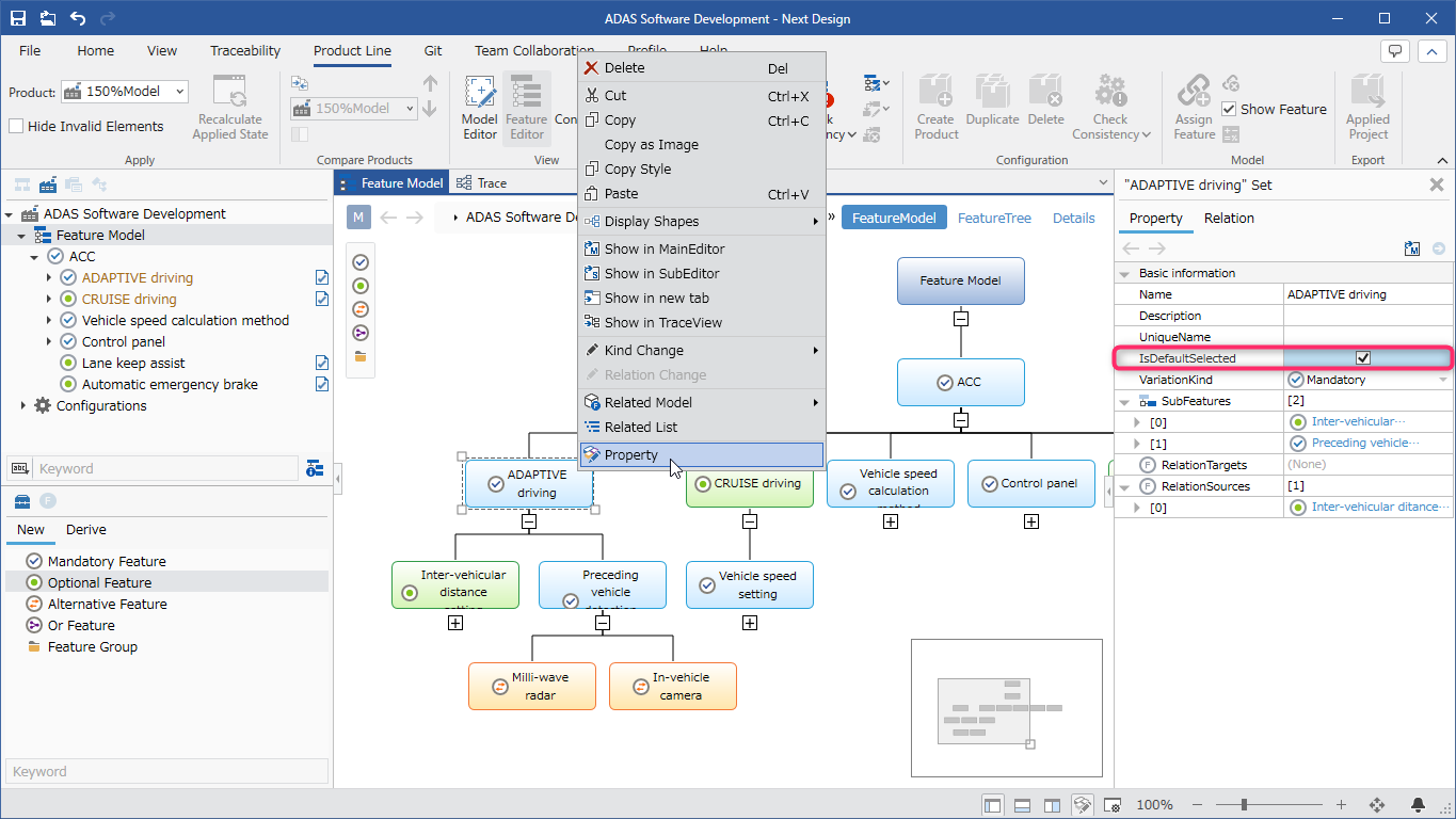
- Right-click the feature and click [Property] in the context menu.
- Check the checkboxes [Property] > [Basic information] > [Initially selected] in the inspector on the right.
- Required features will be selected in the initial state regardless of the check status of [Initially selected].
Write details in feature tree format
To write detailed descriptions for each feature, follow the steps below.
- Switch the view of the feature editor to [Feature tree].
- Edit the Description column of the tree grid.
- The feature tree editor for feature models can add notes to cells.
- To add a note, see Modeling > Edit Model > Edit Tree Grid > Add Note to Cell.
- The feature tree editor for feature models can be exported in Excel format.
- To export in Excel format, see Modeling > Edit Model > Edit Tree Grid > Export in Excel format.
Adding constraints between features
To add constraints between features, follow these steps, similar to adding associations between models in an ER diagram:
- Use drag and drop to associate features with each other.
- Click the type of constraint from the options that pop up.
| Constraint type | Description |
|---|---|
| Exclusion | Represents a relationship in which features with an exclusive constraint cannot be selected at the same time |
| Equals | Represents a relationship in which features with a mutual dependency constraint must be selected at the same time |
| Requires | Represents a relationship in which the dependent feature must be selected when the dependent feature is selected |
You can also add constraints between features by following the steps below.
- Select the source and destination features in the feature editor.
- Click [Product Line] > [Feature] > [Add Feature Relation] from the ribbon and select the type of constraint.
Check the consistency of a feature model
Check consistency
To check the consistency of the structure and constraints of a feature model, follow these steps:
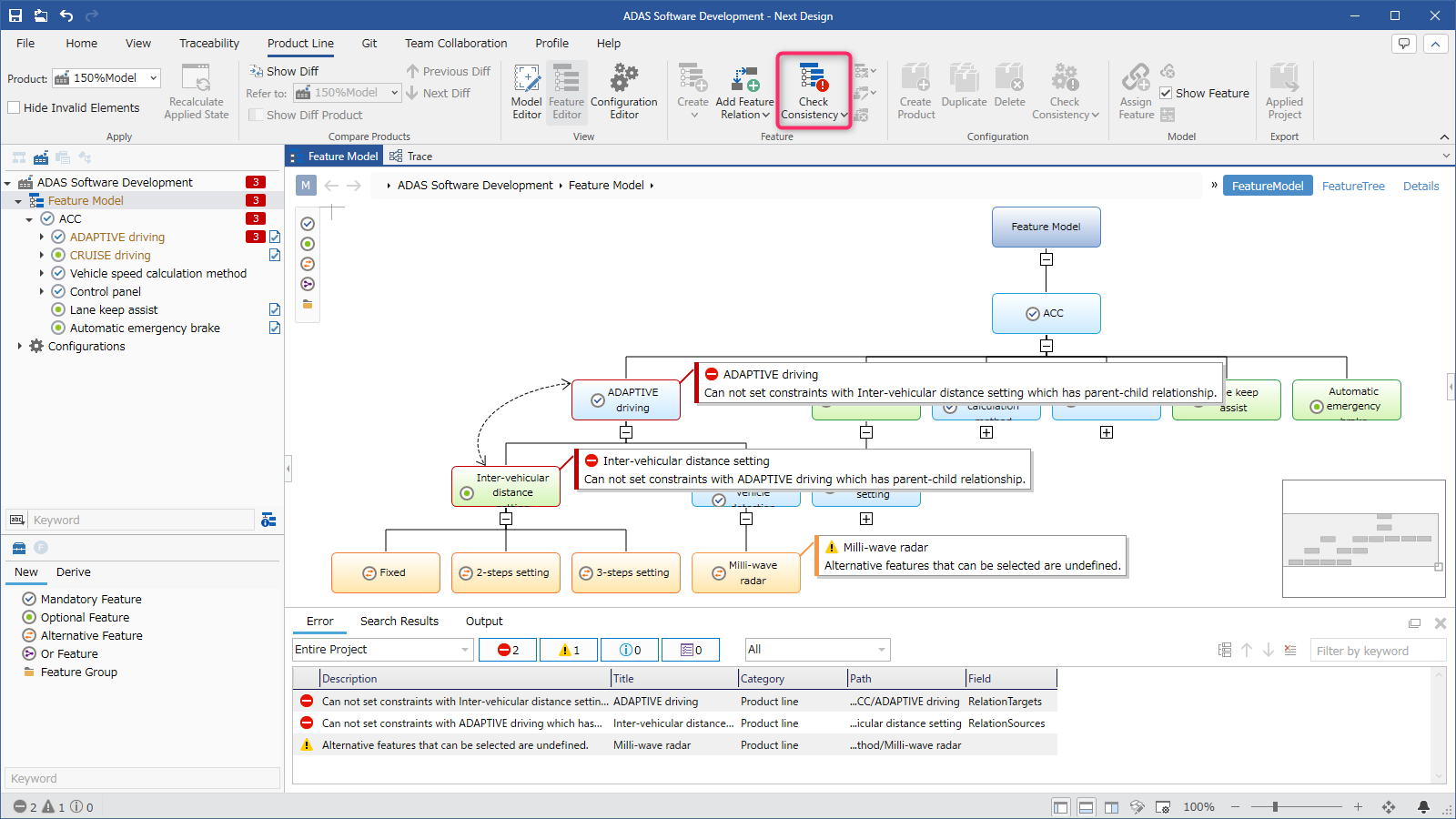
- Click [Feature Model] displayed in the product line on the project screen to switch to the feature editor.
- Click [View] > [Pane] > [Error List] on the ribbon to display the error list.
- Click [Product Line] > [Feature] > [Check Consistency] on the ribbon.
- If there are errors, they will be displayed in the error list and also in the feature editor.
- For details about consistency checks, see Reference > Product Line Development Validation.
Jump to the error
To jump from an error displayed in the error list to the relevant part and fix it, follow the steps below.
- Double-click an error displayed in the error list to jump to the error part on the feature editor.
- Refer to the error message and fix the feature type or the constraint between features.
Cancel the error display
To cancel the error display, follow the steps below.
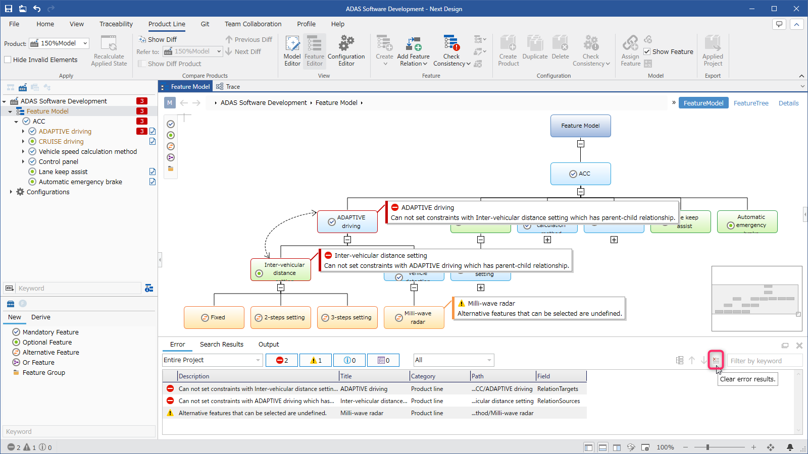
- Do one of the following:
- Click the [Clear error content] button on the error list toolbar.
- From the ribbon, click [Product Line] > [Feature] > [Consistency check] at the bottom, and then click [Clear Error].
Displaying the feature model and tree simultaneously
You can display the [Feature Model] view and [Feature Tree] view of a feature model in separate tabs and switch between them for editing.
To display them in separate tabs, follow the steps below.
- Hover the mouse over the feature model you want to edit and execute the [Show in new tab] command from the context menu.
- Select the feature model selected in step 1 and execute the [Show in new tab] command from the context menu.
- Select the [Feature Tree] view of the feature model displayed in a new tab.
- The [Feature Model] view and [Feature Tree] view of the selected feature model are displayed in new tabs.
You can also display them in new tabs by doing the following:
You can also display tabs by selecting a feature model and dragging and dropping it into the tab area.
- Feature models can be displayed as docked or floating windows.
For information on how to display a docked or floating window, see Model Editing > Model Editing Basics > Opening and Editing Multiple Models Simultaneously.